Magnum Energy MP Extension Box (MPX Series) User Manual
Page 39
3.0 Installation
© 2011 Magnum Energy, Inc.
35
External AC Main Panel Wiring (see Figure 3-21b)
1. Route and attach a black wire from the MP enclosure’s AC LEG 1 IN busbar to the main AC
electrical panel.
2. Route and attach a red wire from the MP enclosure’s AC LEG 2 IN busbar to the main AC
electrical panel.
3. Route and attach a green wire from the MP enclosure’s GROUND busbar to the main AC electrical
panel’s Ground busbar.
4. Route and attach a white wire from the MP enclosure’s AC NEUTRAL busbar to the main AC
electrical panel’s Neutral busbar.
External AC Sub-Panel Wiring (see Figure 3-21b)
1. Route and attach a black wire from the MP enclosure’s AC LEG 1 OUT busbar to the AC electrical
sub-panel.
2. Route and attach a red wire from the MP enclosure’s AC LEG 2 OUT busbar to the AC electrical
sub-panel.
3. Route and attach a green wire from the MP enclosure’s GROUND busbar to the AC electrical
sub-panel’s Ground busbar.
4. Route and attach a white wire from the MP enclosure’s AC NEUTRAL busbar to the AC electrical
sub-panel’s Neutral busbar.
AC Wiring Inspection
After verifying all AC connections are correct, and all AC terminal screws are torqued correctly,
replace the covers on the main electrical panel/sub-panel.
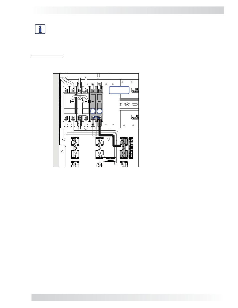
Figure 3-20b, MPXS-60S / MPSL-60S AC Breaker Input Wire Transition
Bottom AC Breaker Wiring (see Figures 3-20b & 3-21b)
Info: Before proceeding any further,
disconnect the black AC LEG 1 IN cable from the
bottom left terminal of the AC breaker and reconnect to the bottom right terminal
as shown in Figure 3-20b
.
• Route and attach a red wire from the bottom terminal of the AC input breaker (B1) to the MP
enclosure’s AC LEG 2 IN busbar.
IMPORTANT:
Prior to installing the MPXS-60S’s external AC wiring, disconnect and then recon-
nect the AC LEG 1 IN black wire from the left breaker (B1) to the newly installed right breaker (B2),
as shown in Figure 3-20b. This ensures that the phase relationship (LEG 1/black on right to LEG 2/
red on left) between the AC input source and the output are correct.
MPSL-60S
Enclosure
B1
B2
NOTE: The AC LEG 1 IN wire is
moved from the B1 position to
the B2 position to ensure correct
input/output phase relationship.