Digital gauge, 2 digital gauge – Retrotec DucTester 341 User Manual
Page 20
Page 20 of 83
©Retrotec Inc. 2014
Figure 5: Fan Pressure sensors are located in the fan inlet.
The 4 Flow sensors are located just inside the fan inlet, behind the protective grill. Together, they
measure the Fan Pressure, from which the fan airflow is calculated in the gauge. If the sensors become
blocked, it is possible to clear them by attaching a pressure tube to the yellow Ref B port, and blowing
air through the tube gently.
The exterior of the inlet has the 4 self-referencing pressure pickups. They are connected to the green
Input B port, and are used as the reference for the Flow (Fan Pressure) Sensors. Self-referencing
ensures that the measured pressure difference is always accurate, no matter what the direction of flow
is with respect to the location of the gauge and operator and whether or not a flex duct is attached to
the inlet of the fan or not.
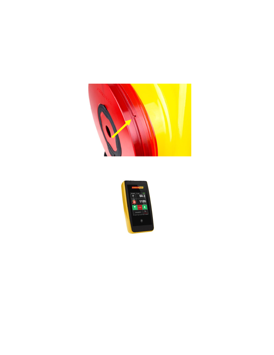
Figure 6: Self-referencing pressure pickup.
5.2
Digital Gauge
Figure 7: DM-32 digital gauge.
Model 341 use the DM32 gauge while Model 342 signifies the WiFi enabled gauge that works exactly the
same in every other respect.
The latest Retrotec Digital Gauge is included with all Retrotec DucTester systems. The gauge can be
combined with the Model 300 fan for automatic control to Set Pressure or Set Speed. The gauge is a
dual-channel manometer, which can automatically convert the measured Fan Pressure into a range of
useful results that meet every major testing standard in the world.
The gauge is also capable of taking a Baseline pressure reading, and automatically recalculating results,
in order to reflect this bias pressure. It can auto zero itself to ensure pressure readings do not drift away
from the true pressure value during a test. It is also capable of displaying results that are extrapolated
to any pressure.
For more information on configuring and using the DM-32, see the DM-32 Operation Manual.