Make all connections on the gauge and fan, Flat faces down, 5 make all connections on the gauge and fan – Retrotec DucTester 341 User Manual
Page 26
Page 26 of 83
©Retrotec Inc. 2014
6.5
Make all connections on the gauge and fan
1. Often, the yellow, green and blue tubes and the Control Cable are left permanently
connected to the gauge but if not, make those connections.
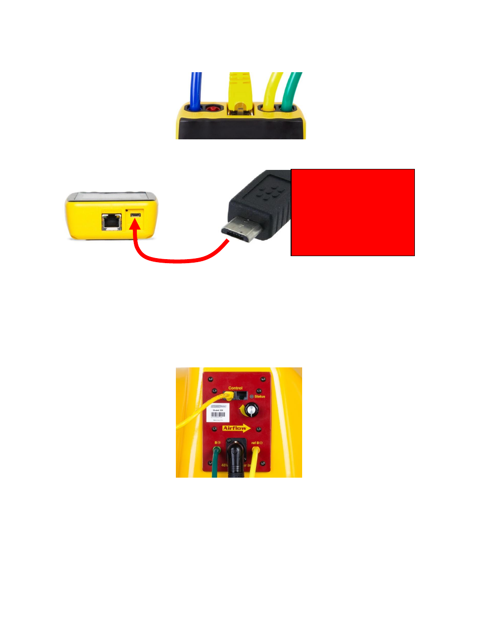
Figure 13: Pressure ports on the top of the gauge are color-coded to match the tubing.
Figure 14: Electrical connections on the bottom of the gauge include Network (Ethernet) Cable that goes from the DM32 to a
PC (if Retrotec PC software is used for data collection), micro USB cable for PC software and/or charging, and a reset button.
2. Connect the power cord to a wall outlet and to the fan. Turn on the power switch. The
Mains Power status light turns green, indicating power is connected. Before connecting the
Control Cable, the manual speed control knob can be used to test run the fan. If the Control
Cable is connected it must be disconnected to use the Manual Speed Control Knob. The
Manual Speed Control Knob must be turned to zero and back on again to re-activate it.
Figure 15: Model 300 Fan Top houses the speed control, control knob, power connection, color-coded tubing connections
(green and yellow) and Control Cable.
3. Connect the Control Cable to the fan, unless you wish to use the Manual Speed Control
Knob. When the Control Status light is illuminated solid green, this means the fan is
connected to the gauge and is ready to perform automated testing. Having the Speed
Control Cable connected disables the manual Speed Control Knob. To enable the manual
Flat faces down
Flat portion of Micro USB must
face down and rounded portion
must face up for charging or
connecting to your computer. Icon
on some cables may have to face
down.