RIGOL DP832 User Manual
Page 30
RIGOL
1-12
DP800 User’s Guide
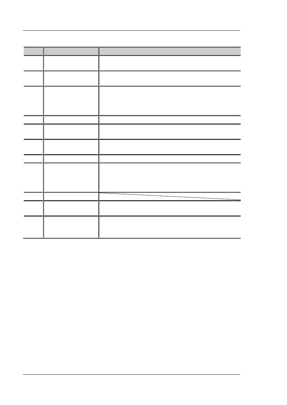
Table 1-1 DP800 rear panel explanation
No.
Name
Explanation
1
LAN Interface
(option)
The instrument is connected to the local network via
RJ45 interface
2
USB DEVICE
Connect the instrument (as "slave" device) to
external USB device (such as PC)
3
USB HOST
Connect the instrument (as "host" device) to external
USB device (such as USB storage device);
extend a GPIB interface for the power supply using
USB-GPIB interface converter (option)
4
Digital I/O (option) Digital I/O interface
5
RS232 Interface
(option)
Serial communication interface
6
Voltage Selector
Select the specification of the input voltage (100, 115
or 230; please refer to Table 1-2)
7
Power Socket
AC power input interface.
8
Fuse
The specification of the fuse is related to the
instrument model and actual input voltage (please
refer to the "Input Power Requirements" at the rear
panel of the instrument or refer to Table 1-3).
9
Fan
10
Input Power
Requirement
Corresponding relations of the AC input power
frequency, voltage and the specification of the fuse.
11
Output Interface
DP811 provides this interface. The function of this
interface is the same as that of the "Output
Terminals" at the front panel.
Note: The "Output Terminals" at the front panel and "Output Interface" at the rear
panel cannot be used for output at the same time. You can only select one of them
for output at each time (wherein, the output terminals at the front panel provide
higher output accuracy).