Table 2-1. input/output pin assignments, Figure 2-2. tma vxi-27 front panel, Tma vxi-27 front panel -3 – KEPCO TMA VXI-27 User Manual
Page 16: Input/output pin assignments -3, Figure 2-2.), E 2-1 for
Advertising
TMA VXI -27 101602
2-3/(2-4 Blank)
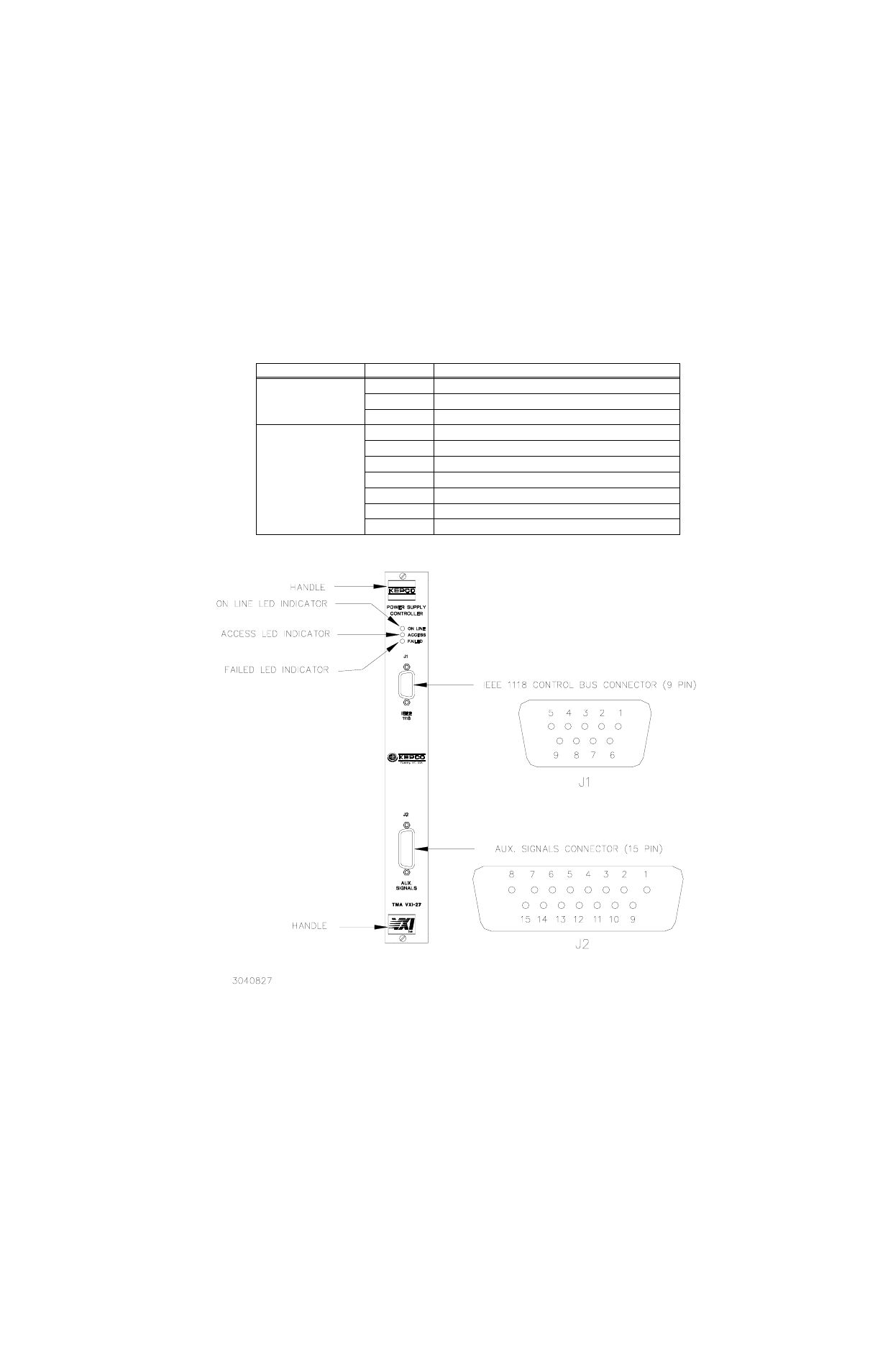
FIGURE 2-2. TMA VXI-27 FRONT PANEL
TABLE 2-1. INPUT/OUTPUT PIN ASSIGNMENTS
CONNECTOR
PIN
FUNCTION
IEEE 1118
(9-Pin, D-type, female)
1, 2, 6, 7
Ground
3, 4, 5
IEEE 1118 (2-Wire Differential Interface)
8, 9
IEEE 1118 (2-Wire Differential Interface)
AUX. SIGNALS
(15-Pin, D-type, female)
1, 7. 8
Emergency Shut-down - Isolated Input Cathode (–)
2, 5, 6
Emergency Shut-down - Isolated Input Anode (+)
3, 4
+5v Output (Through 390 Ohm)
9, 11
Ground
10
Emergency Shut-down Input - Non Isolated
12, 13
Discrete Fault Line - Relay Contact Pin 1
14, 15
Discrete Fault Line - Relay Contact Pin 2
Advertising