KEPCO TMA VXI-27 User Manual
Page 22
TMA VXI -27 101602
3-5
INIT (switch)
Click to select a different controller. If only one controller is installed, it will be automat-
ically selected.
SYS RESET (switch)
Click to reset all power supplies connected to the selected controller (power supplies
are reset to initial power-on condition)
CHAN RESET (switch)
Click to reset only the selected power supply (power supply is reset to initial power-on
condition)
OUTPUT (switch)
Click to enable or disable the selected power supply output. (Operates relays on
power supply models with relays; otherwise output voltage and current is set to zero.
POLARITY (switch)
Click to reverse polarity of power supply models incorporating polarity reversal fea-
ture.
MODE (switch)
Click to select Constant Voltage or Constant Current (alternate action).
TEST (switch)
Programs all power supplies connected to the controller to their maximum value,
resets them, opens all relays (if present), then checks for errors in output. If error is
detected, the channel number of the failed unit is selected, and the status values indi-
cate the type of error detected.
MEASURED
OUTPUT
(indicators)
VOLTAGE meter
Provides analog and digital indication of measured voltage.
CURRENT meter
Provides analog and digital indication of measured current
OUTPUT
CONTROLS
VOLTAGE
Click on arrows to set voltage. If AUTOEXECUTE is set to ON, voltage value is imme-
diately applied to power suply. If AUTOEXECUTE is set to OFF, voltage value is not
applied to selected power supply until EXECUTE is clicked.
CURRENT
Click on arrows to set current. If AUTOEXECUTE is set to ON, current value is imme-
diately applied to power suply. If AUTOEXECUTE is set to OFF, current value is not
applied to selected power supply until EXECUTE is clicked.
EXECUTE
(switch)
With AUTOEXECUTE set to OFF, click to apply VOLTAGE and CURRENT values to
selected power supply.
AUTOEXECUTE
ON/OFF
(switch)
Click to set ON/OFF (alternate action). When set to OFF, EXECUTE must be clicked
to apply VOLTAGE and CURRENT values to selected power supply. When set to ON,
VOLTAGE and CURRENT values are immediately applied to the selected power sup-
ply.
ACTIVE (indicator)
Lights (green) to indicate controller is active.
SLOT (indicator)
Displays slot of active controller
READ (indicator)
Lights (green) to indicate controller is reading infirmation from power supply.
FAULT (indicator)
Lights (red) to indicate error detected. Error indicated by STATUS register values.
OUTPUT ON (indicator)
Lights (green) when power supply output is enabled.
REVERSED (indicator)
Lights (green) when power supply output polarity is reversed.
CV (indicator)
Lights (green) when power supply is in Constant Voltage mode. (If the Voltage Limit is
exceeded while the power supply was programmed to be in Constant Current mode,
the power supply will be forced into Constant Voltage mode (CV turns green) and the
FAULT indicator lights (red).
CC (indicator)
Lights (green) when power supply is in Constant Current mode. (If the Current Limit is
exceeded while the power supply was programmed to be in Constant Voltage mode,
the power supply will be forced into Constant Current mode (CC turns green) and the
FAULT indicator lights (red).
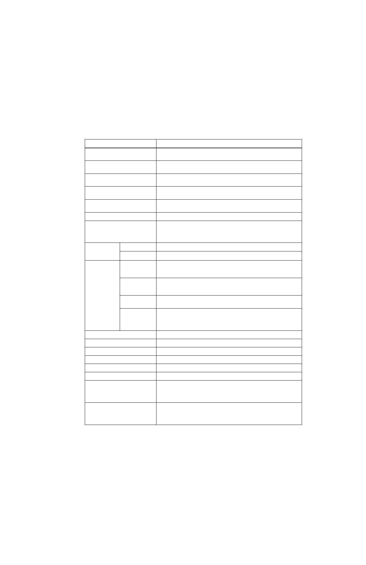
TABLE 3-1. Plug&play PANEL CONTROLS AND INDICATORS (CONTINUED)
CONTROL/INDICATOR
FUNCTION