Assigning a video source to channel 3, Switching the view mode of preview output, P. 16 – Roland V-1SDI 4-Channel HD Video Switcher User Manual
Page 16: T video (p. 16, 16 video input/output settings
16
Video Input/Output Settings
Assigning a Video Source to
Channel 3
By factory default, the selection of SDI input or
HDMI input for channel 3 is set to “AUTO” (automatic
detection of the connection). When devices are
connected to both the SDI IN 3 connector and the
HDMI IN 3 connector, SDI input takes precedence.
When you want to input video via a specified
connector, change this setting.
1.
Display the SETUP menu (p. 12), then select
“CH3 INPUT SELECT.”
2.
Use the A/B fader to specify the video source to
input on channel 3.
Value
Explanation
AUTO
The connector where the connection is made
is automatically detected and video is output.
When devices are connected to both the SDI
IN 3 connector and the HDMI IN 3 connector,
SDI input takes precedence.
SDI
Video is input only via the SDI IN 3 connector.
HDMI
Video is input only via the HDMI IN 3
connector.
3.
Switching the View Mode of
Preview Output
Three types of view modes are available for the
V-1SDI’s preview output. You can set the view mode
individually for the PVW connector (SDI) and the
MULTI-VIEW connector (HDMI).
1.
Display the SETUP menu (p. 12), then select
“PVW ASSIGN” (PVW connector) or “OUTPUT
ASSIGN” (MULTI-VIEW connector).
2.
Use the A/B fader to set the view mode.
Value
Explanation
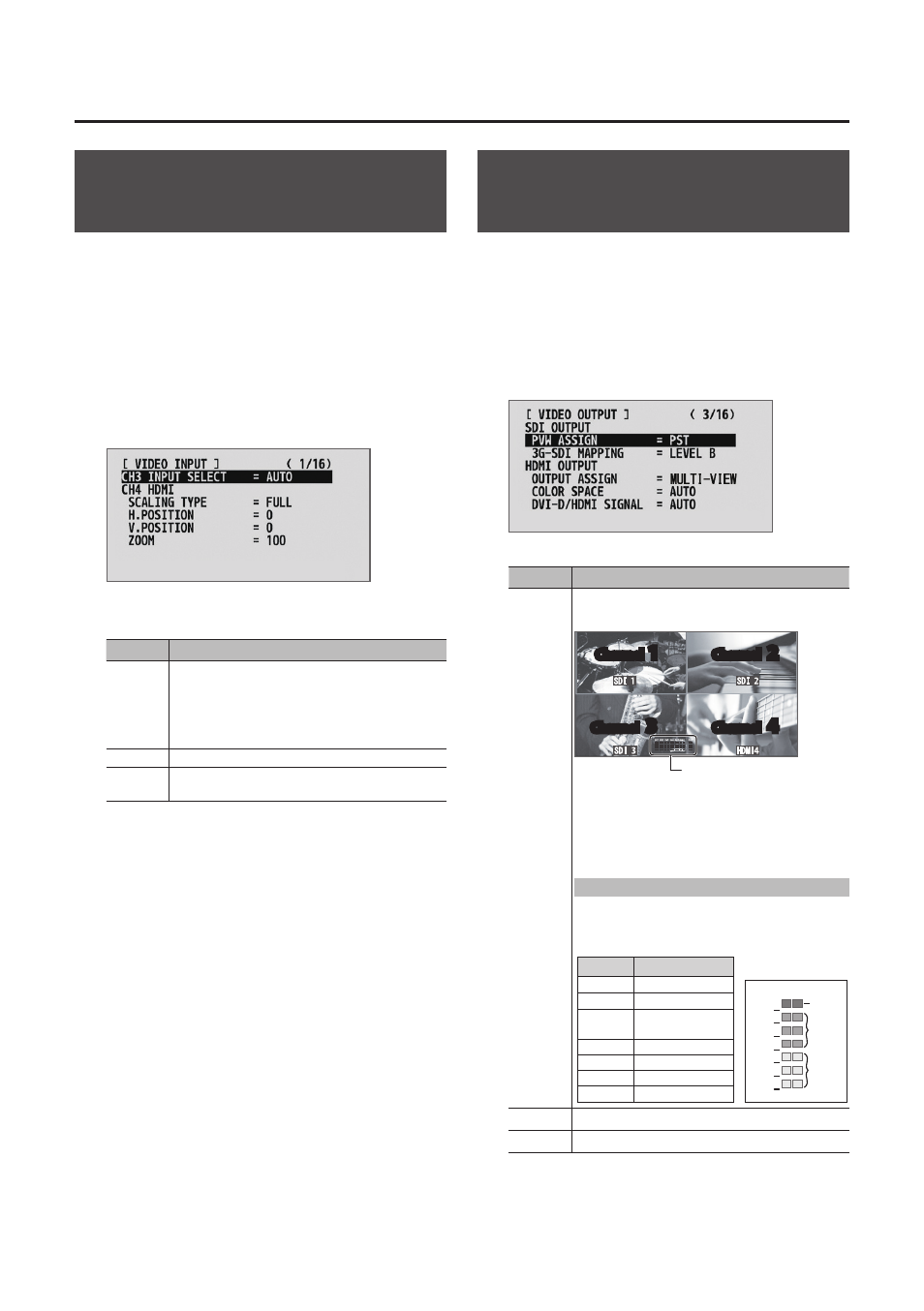
MULTI-
VIEW
This displays the incoming video on channels
1 through 4 as a four-way split screen.
Audio level meter
Channel
1
Channel
2
Channel
3
Channel
4
The video is displayed with a colored border
that is interlinked with the selected [A-1]
through [A-4] or [B-1] through [B-4] button.
Red border: Video currently being output
Green border: Video to be output next
Displaying the audio level meter
* This is displayed at the bottom of the
screen only for output from the MULTI-VIEW
connector (HDMI).
Indication Input/output name
IN1
SDI IN 1
IN2
SDI IN 2
IN3
SDI IN 3 or
HDMI IN 3
IN4
HDMI IN 4
AUD
AUDIO IN
MIC
MIC
OUT
MASTER OUT
Level
0
-6
-10
-20
-30
-40
-50
(dB)
Yellow
Red
Green
PGM
This displays the video currently being output.
PST
This displays the video to be output next.
* Labels for identifying SDI and HDMI in all view modes
are displayed only for output from the MULTI-VIEW
connector (HDMI).
3.