Nexen RSTC1100 964528 User Manual
Page 15
15
FORM NO. L-21204-C-0705
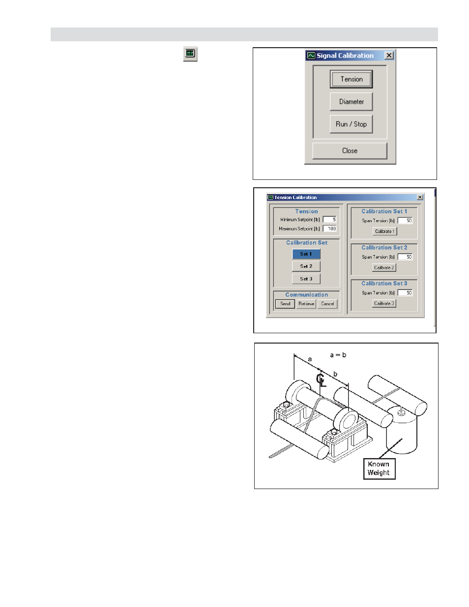
Figure 15
Signal Calibration
Figure 16
Tension Calibration
TENSION SIGNAL CALIBRATION
Set the Maximum Tension Setpoint before calibrating
tension sensors. Afterwards, re-calibration of tension
sensors is required whenever the Maximum Tension
Setpoint is changed.
Minimum Tension Setpoint: Enter minimum tension level
that will be run on the machine in the designated imperial or
metric units. The choice of units is determined by selecting
the DISPLAY icon and then selecting Imperial or Metric
in the UNITS pane.
Maximum Tension Setpoint: Enter maximum tension level
that will be run on the machine in the designated imperial or
metric units. The choice of units is determined by selecting
the DISPLAY icon and then selecting Imperial or Metric
in the UNITS pane.
NOTE: Selection of tension setpoints outside these
limits will not be allowed by the RSTC and the Minimum
Tension Setpoint will limit taper tension’s minimum
tension.
Calibration Set: Select Set 1, Set 2 or Set 3
The RSTC allows the use of three different sets of
calibration values for converting load cell output voltages
into tension values. These calibration sets can be used for
different web paths that utilize the same set of load cells
and have different web wrap angles.
1. Press
TENSION (See Figure 16).
2. Under Calibration Set 1, enter the web tension that
will be used to calibrate the span condition into the
SPAN TENSION box . Span Tension is equal to the
weight as shown in Figure 17 and should be set as
close as practical to MAXIMUM SETPOINT.
3. Press CALIBRATE 1.
4. Unload the tension sensing roller and then press
OK. The tare condition, which is the weight of the
roller, has just been recorded.
5. Load the tension sensing roller, as shown in Figure
17, using the amount of web tension entered for
SPAN TENSION in step 2 and then press OK.
6. Unload the tension sensing roller and then press
OK. The tare condition is rechecked and the
calibration process is completed.
SIGNAL CALIBRATION
SIGNAL CALIBRATION WINDOW
Select the SIGNAL CALIBRATION
icon from the toolbar. (See Figure 15).
Figure 17
For other web paths using the same load cells, repeat
steps 1–6 for Calibration Set 2 and Set 3.
7. To select a calibration set to be used, select
Calibration Set 1, Set 2, or Set 3 and press SEND.