Configuration details, Configuration sequence, Configuration details -23 – Altera MAX 10 FPGA User Manual
Page 27: Configuration sequence -23
Configuration Details
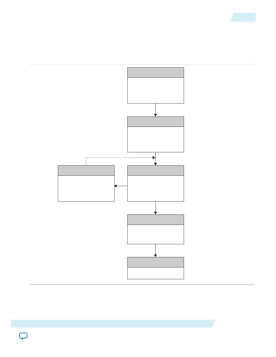
Configuration Sequence
Figure 2-10: Configuration Sequence for MAX 10 Devices
Power supplies including V
CCIO
, V
CCA
and V
CC
reach recommended operating voltage
nSTATUS and nCONFIG released high
CONF_DONE pulled low
CONF_DONE released high
Power Up
• nSTATUS and CONF_DONE
driven low
• All I/Os pins are tri-stated
• Clears configuration RAM bits
Reset
• nSTATUS and CONF_DONE remain low
Initialization
• Initializes internal logic and
registers
• Enables I/O buffers
Configuration Error Handling
• nSTATUS pulled low
• CONF_DONE remains low
• Restarts configuration if option
enabled
User Mode
Executes your design
Configuration
Writes configuration data to
FPGA
• All I/Os pins are tri-stated
• Samples CONFIG_SEL pin
You can initiate reconfiguration by pulling the
nCONFIG
pin low to at least the minimum t
CFG
low-pulse
width. When this pin is pulled low, the
nSTATUS
and
CONF_DONE
pins are pulled low and all I/O pins are
tied to an internal weak pull-up.
UG-M10CONFIG
2015.05.04
Configuration Details
2-23
MAX 10 FPGA Configuration Schemes and Features
Altera Corporation