Fpga programming from flash memory, Fpga programming from flash memory –16 – Altera DSP Development Kit, Stratix V Edition User Manual
Page 24
2–16
Chapter 2: Board Components
Configuration, Status, and Setup Elements
DSP Development Kit, Stratix V Edition
July 2012
Altera Corporation
Reference Manual
The secondary method is to use the pre-built PFL design included in the development
kit. The development board implements the Altera PFL megafunction for flash
programming. The PFL megafunction is a block of logic that is programmed into an
Altera programmable logic device (FPGA or CPLD). The PFL functions as a utility for
writing to a compatible flash device. This pre-built design contains the PFL
megafunction that allows you to write either page 0, page 1, or other areas of flash
over the USB interface using the Quartus II software. Use this method to restore the
development board to its factory default settings.
Other methods to program the flash can be used as well, including the Nios II
processor.
f
For more information on the Nios II processor, refe
page of
the Altera website.
FPGA Programming from Flash Memory
On either power-up or by pressing the program load push button (S2), the MAX V
CPLD System Controller’s parallel flash loader configures the FPGA from the flash
memory. The system controller uses the Altera Parallel Flash Loader (PFL)
megafunction which reads 32-bit data from the flash memory and converts it to fast
passive parallel (FPP) format. This 32-bit data is then written to the dedicated
configuration pins in the FPGA during configuration.
After a power-up or reset event, the MAX V CPLD (U4) automatically configures the
FPGA in FPP mode with either the pre-installed factory .pof file or a user .pof file
depending on the setting of the PGM_SEL push-button (S3). There are three pages
reserved for the FPGA configuration data—factory hardware (page 0), user
hardware 1 (page 1), and user hardware 2 (page 2). There are three green
configuration status LEDs, PGM_LED[0:2] (D4, D5, D6), which indicates the status of
the FPP configuration.
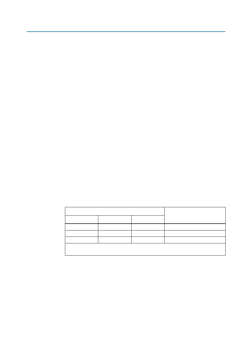
lists the configuration status LEDs settings.
Table 2–9. Configuration LED settings
LED
Design
PGM_LED0
PGM_LED1
PGM_LED2
v
—
—
Factory
—
v
—
User hardware 1
—
—
v
User hardware 2
Note to
(1) A checkmark (
v) indicates that the LED is ON (logic 0) while a dash (—) indicates that the LED is OFF (logic 1).