Clock circuitry, On-board oscillators, Clock circuitry –23 – Altera DSP Development Kit, Stratix V Edition User Manual
Page 31: On-board oscillators –23
Chapter 2: Board Components
2–23
Clock Circuitry
July 2012
Altera Corporation
DSP Development Kit, Stratix V Edition
Reference Manual
Clock Circuitry
This section describes the board's clock inputs and outputs.
On-Board Oscillators
The development board includes a 50-MHz, 100-MHz, 125-MHz, and 156.25-MHz
programmable oscillators.
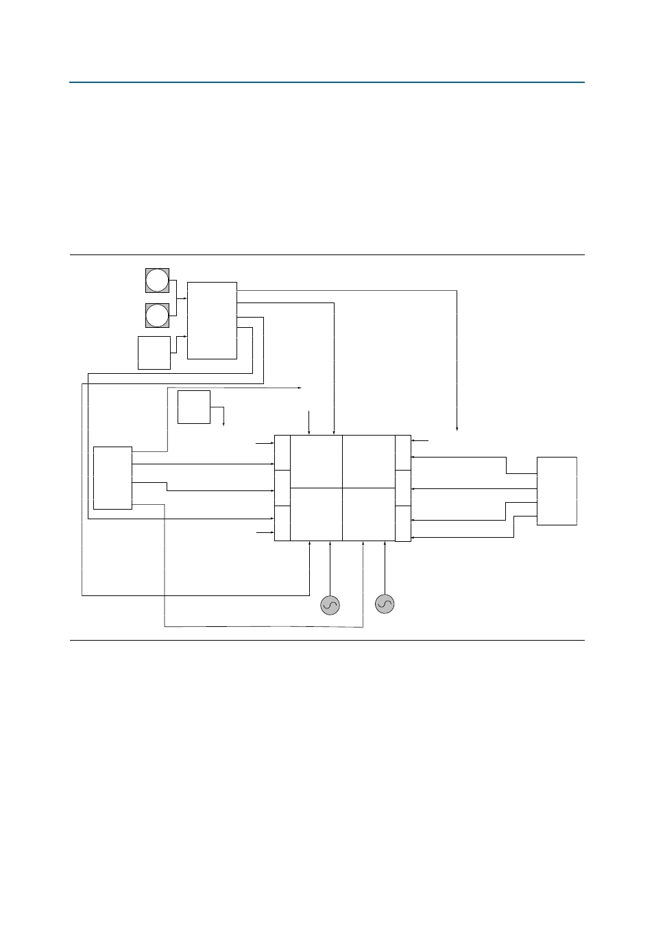
shows the default frequencies of all external
clocks going to the development board.
Figure 2–5. DSP Development Kit, Stratix V Edition External Clock Inputs and Default Frequencies
SMA
REFCLK INPUT
SMA
Buffer
(100 MHz
Default)
Si570
(100 MHz
Default)
Si5388
156.25 MHz
625 MHz
270 MHz
100 MHz
REFCLK4_QR2_P/N
REFCLK5_QR2_P/N (HSMB)
REFCLK2_QR1_P/N (HSMB)
REFCLK1_QR0_P/N (HSMA)
REFCLK0_QR0_P/N (HSMA)
644.53125 MHz
282.5 MHz
125 MHz
125 MHz
125 MHz
100 MHz
100 MHz
100 MHz
100 MHz
CLK4
CLK0
CLK6
CLK22
CLK16
CLK9
REFCLK5_QL2_P/N (148.5 MHz)
SDI (148.5 M / 148.35 M)
REFCLK4_QL2_P/N (QSFP)
REFCLK2_QL1_P (QSFP)
REFCLK1_QL0_P/N
PCIE_REF_CLK_P/N
CLKINT
OP_P/N[1]
CLKINT
OP_P/N[0]
CLKIN_50
CLKINBO
T_P/N[0]
CLK_125_P/N
CLKINBO
T_P/N[1]
Si5388
CLK3
CLK2
CLK1
CLK0
Si571
148.5 MHz
Default
B8
QL2
QL1
QL0
B3
B4
B7
QR2
QR1
QR0
CLK3
CLK2
CLK1
CLK0
50 M
125 M