8 optical fiber input cable connection – Holland Electronics NE 1100 User Manual
Page 18
18
NE1100A2 CATV Optical Receiver Operation Manual
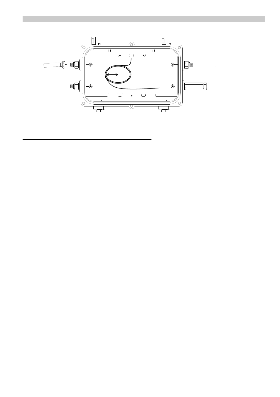
Figure 7. Fiber Cable Installation
5.8 Optical Fiber Input Cable Connection
The standard fiber connector is FC/APC, however FC/APC or SC/APC can be used
according to the system configuration. Confirm which type of fiber connector is used in the
system.
A dust cover should be installed whenever there is no optical fiber cable installed to protect
the receiver’s fiber cable input port.
The NE1100 optical receiver uses a dedicated pigtail cable (a “jumper cable” or length of
optical cable included) used to connect to the fiber cable’s connection box and optical
transceiver node.
1. Remove the weather tight plug from port D.
2. Bring the fiber cable into optical receiver housing at port D, using a threaded waterproof
sleeve fitting (see fig. 7).
3. Carefully rest the receiver chassis (with the top panel open) sideways atop the receiver
housing. Bring the fiber cable up through the bottom of the receiver chassis through the
cutout corner of the PCB.
4. Position the receiver chassis into the receiver housing, using the guide slots near the
hinges to position the chassis. Be careful not to pinch or kink the fiber optic cable. Tighten
the 3 screws at points a, b, & c (see fig.5).
5. Reconnect the 6-conductor wiring harness from the DC power supply to connector J2 on
the receiver PCB.
6. Completely tighten the weatherproof sleeve fitting against the receiver housing at port D.
Also tighten the weatherproof nut on the fiber cable.
Pin Connector
A
B
C
D
C
D
3cm