0 principals of operation – Holland Electronics NE 1100 User Manual
Page 6
6
NE1100A2 CATV Optical Receiver Operation Manual
3.0 Principals of Operation
The NE1100 series optical receiver converts an optical input signal into an RF output signal.
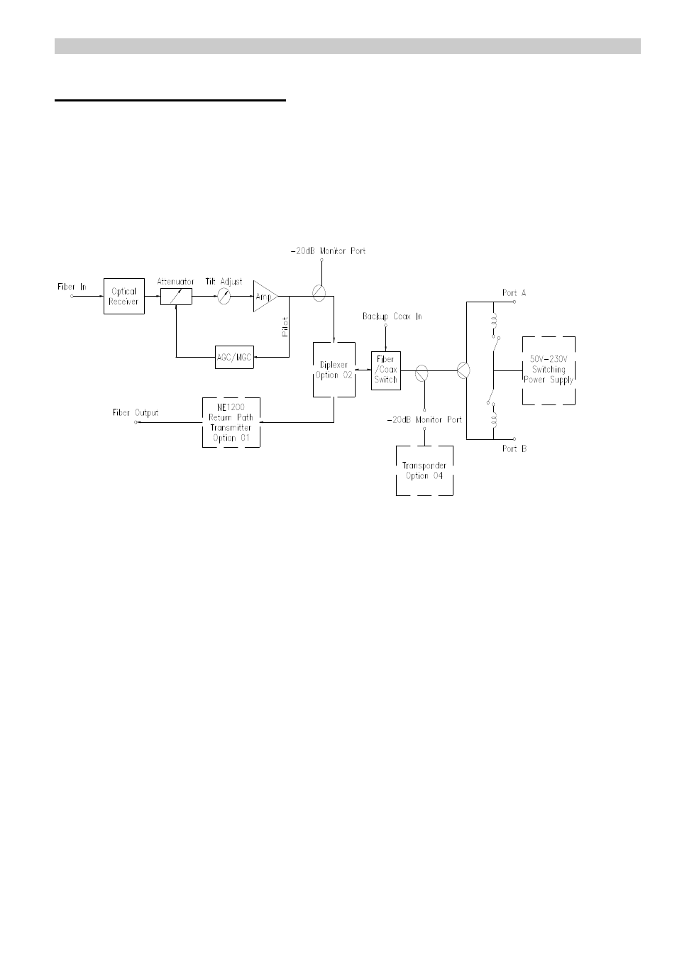
The block diagram in figure 1 highlights the functions of the receiver.
Figure 1. NE1100 Functional Block Diagram
The Optical Receiver (1) detects the input optical signal, converts it into an RF signal, and also
converts it into voltage signal via the front end amplifier. By using the Equalizer (2) and Tilt
Adjustment (3), the dB level can be set according to the practical needs of the Amplifier (4),
which sends the RF signal to the Pilot-Tone Power Detector (5) which detects the guided signal
strength used for feedback control of the AGC automatic and MGC manual gain control
circuits (6).
The amplified RF signal is sent to the Diplexer (option 02) and to the Fiber/Coax Switch (7).
From there the RF signal is sent to the RF Output Ports A & B. The Backup Coax In port (8)
serves as an auxiliary RF input to keep the system functioning in case the optical input signal to
the receiver is lost. The RF output level of the receiver can be measured at the –20dB Monitor
Port. The signal strength should be –20dB (+/-1 dB) down from the output signal at port A.
A Transponder (option 04) can be installed at the 14-pin Status Monitor Port (see fig. 3) to
transmit the receiver’s status information to the network status monitor.
A Return Path Transmitter (option 01) can be installed to return an optical signal to the headend ,
including the monitor signal , which is sent via a repeater.
#
1
#
2
#
3
#
5
#
4
#
6
#
7
#
8