Nvis2310 connector specification & jumper setting – NEXCOM NViS 2310 User Manual
Page 33
Advertising
Copyright © 2013 NEXCOM International Co., Ltd. All Rights Reserved.
19
Chapter 3: Jumpers and Switches
NViS2310 User Manual
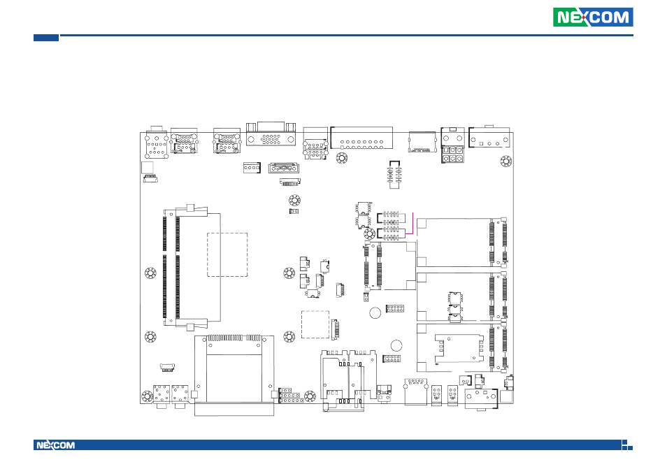
NViS2310 Connector Specification & Jumper Setting
NViS2310 carrier board placement
The figure below is the carrier board used in the NViS2310 system. It shows the locations of the jumpers and connectors.
J1
JP5
DIMM1
CN6
J9
J8
SW9
J2
JP2
JP3
JP4
J12
SW1
J14
J13
JP6
JP8
CN17
JP7
CN24
SW8
J20
J21
J22
CN25
CN26
CN27
SW6
SW7
J17
SW3
CN20
CN18 CN19
SW4
CN10
CN9
CN7
Advertising
This manual is related to the following products: