Dip switch settings, Rtc clear selection, Gpio pull-high setup – NEXCOM NViS 2310 User Manual
Page 34
Advertising
Copyright © 2013 NEXCOM International Co., Ltd. All Rights Reserved.
20
Chapter 3: Jumpers and Switches
NViS2310 User Manual
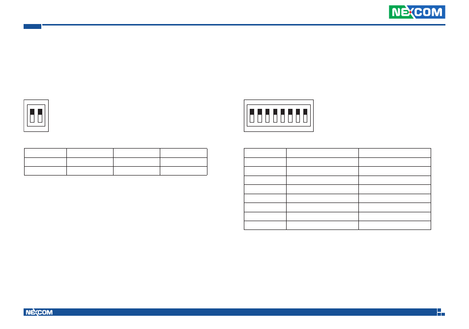
DIP Switch Settings
RTC Clear Selection
Connector location: SW1
Normal(*)
Clear ME
Clear CMOS
SW1.1
OFF
OFF
ON
SW1.2
OFF
ON
OFF
(*) Default
ON
OFF
SW2.1
GPIO1 Pull-High 5V
Open
SW2.2
GPIO 2 Pull-High 5V
Open
SW2.3
GPIO 3 Pull-High 5V
Open
SW2.4
GPIO 4 Pull-High 5V
Open
SW2.5
GPIO 5 Pull-High 5V
Open
SW2.6
GPIO 6 Pull-High 5V
Open
SW2.7
GPIO 7 Pull-High 5V
Open
SW2.8
GPIO 8 Pull-High 5V
Open
GPIO Pull-High Setup
Connector location: SW2
1
O
N
2
1
O
N
2 3 4 5 6 7 8
Advertising
This manual is related to the following products: