NEXCOM VMC 3000/ 3001 User Manual
Page 119
Copyright © 2012 NEXCOM International Co., Ltd. All rights reserved
103
VMC 3000/4000 Series User Manual
Chapter 7: Touchscreen Installation Guide
Plot Calibration
Data
Check this function to have touch panel linearity
comparison graph appear when you finish
Advanced Calibration. The black lines reflect
the ideal linearity assumed by PenMount’s
application program while the blue lines show the
approximate linearity calculated by PenMount’s
application program as the result of user’s
execution of Advance Calibration.
Turn off EEPROM
storage
This function disables the write-in of calibration
data in Controller. This function is enabled by
default.
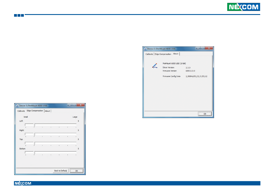
Edge Compensation
This page is the edge compensation settings. You can adjust the settings
from 0 to 30 for accommodating the difference of each touch panel.
About
This panel displays information about the PenMount controller and driver
version.