NEXCOM NSA 5130 User Manual
Page 105
Copyright © 2011 NEXCOM International Co., Ltd. All Rights Reserved.
92
NSA 5130 User Manual
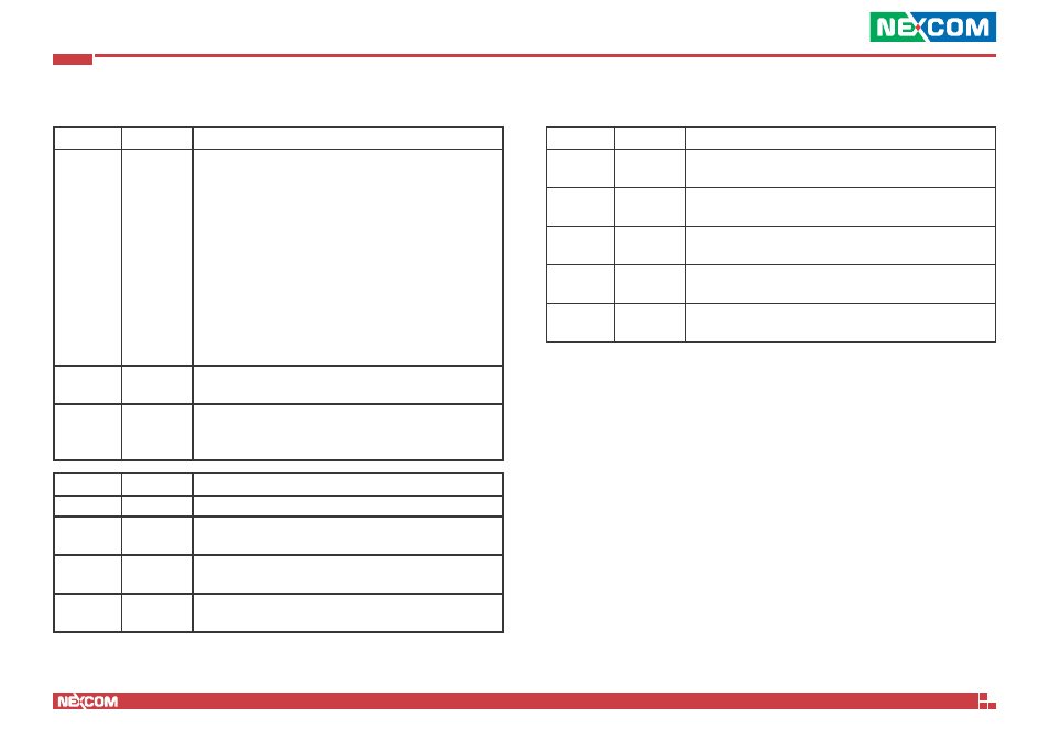
Appendix C: Bypass Specifications
Power ON State Bypass Control Status Register F3
Bit Field
Name
Value
1:0
Segment
1 to 2
Segment control bit mask. Each bit corresponds to a spe-
cific segment numbered 1 thru 3.
Write:
If a segment mask bit is set to false (0) no action on that
segment will take place.
If a segment mask bit has been set to true (1), action will
take place on this segment according to the bypass mode
settings in bits 7:6.
Read:
Upon read operations the bit mask returned indicates true
(1) for those segments which have been enabled and false
(0) for those segments which are disabled.
2-5
Not used
No active taken if written, value is undetermined and not
needed on read operation.
7:6
Bypass
Mode
These two bits defined the bypass mode for one or more
segments. These bits are Write only and on reads returns
undetermined values which will be ignored by the driver.
Bit 7
Bit 6
Action
0
0
Ignore, no action taken.
0
1
Force Enable - Engage bypass relays on segments enabled
in segment mask.
1
0
Force Disable - Disable bypass relays immediately on seg-
ments enabled in mask.
1
1
Timer Enable - Segments enabled in mask are under Timer
control.
Power OFF state Bypass Control Status Register F7
Bit Field
Name
Value
0
Segment 1
0 = Set segment bypass disable when power off
1 = Set segment bypass enable when power off
1
Segment 2
0 = Set segment bypass disable when power off
1 = Set segment bypass enable when power off
2
Segment 3
0 = Set segment bypass disable when power off
1 = Set segment bypass enable when power off
3
Segment 4
0 = Set segment bypass disable when power off
1 = Set segment bypass enable when power off
7:4
Not used
No active taken if written, value is undetermined and not
needed on read operation.