Connector pin definitions, External i/o interface – NEXCOM NSA 5130 User Manual
Page 27
Advertising
Copyright © 2011 NEXCOM International Co., Ltd. All Rights Reserved.
14
NSA 5130 User Manual
Chapter 2: Jumpers and Connectors
External I/O Interface
Connector Pin Definitions
Status Indicators
Connector location: LED9
Status
LED Color
PWR
Green
HDD
Yellow
F6 0
Yellow
F6 1
Yellow
GPIO (F6 bit1)
GPIO (F6 bit0)
PWR
HDD
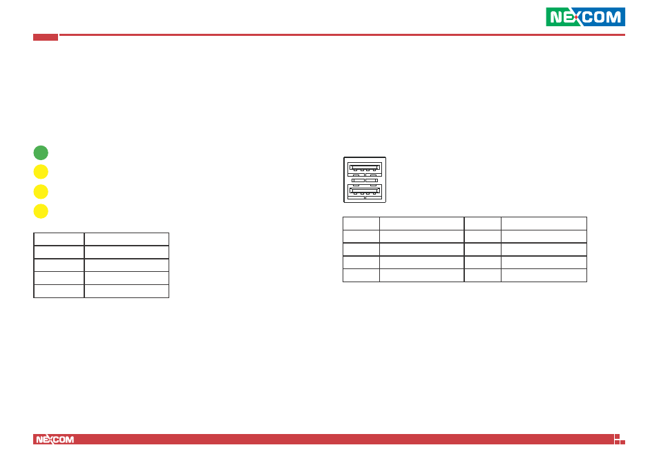
USB Ports
Connector type: Dual USB port
Connector location: CN1
Pin
Definition
Pin
Definition
1
VCC
5
VCC
2
USB0-
6
USB1-
3
USB0+
7
USB1+
4
GND
8
GND
Advertising
See also other documents in the category NEXCOM Hardware:
- EBC 352 (68 pages)
- EBC 353 (62 pages)
- EBC 355 (63 pages)
- EBC 354 (63 pages)
- ICES 268 (96 pages)
- ICES 667 (100 pages)
- ICES 254 (98 pages)
- NEX 604 (61 pages)
- NEX 608 (67 pages)
- ICES 668 (105 pages)
- NEX 607 (75 pages)
- NEX 609 (61 pages)
- NEX 611 (51 pages)
- NEX 613 (45 pages)
- NEX 617 (53 pages)
- NISE 101 (79 pages)
- NISE 104 (78 pages)
- NISE 2020 (84 pages)
- NISE 105A (78 pages)
- NISE 103 (83 pages)
- NISE 2110A (87 pages)
- NISE 2420 (84 pages)
- NISE 301 (74 pages)
- NISE 2310E (107 pages)
- NISE 2210E (110 pages)
- NISE 3100eP2 (75 pages)
- NISE 300 (95 pages)
- NISE 3140P2E (88 pages)
- NISE 3520P2E (125 pages)
- MAC 3500P2-GTS8 (120 pages)
- NISE 3600E (102 pages)
- NISE 3720P2E (85 pages)
- NISE 3640P2E (105 pages)
- NISE 3640M2E (108 pages)
- NISE 4000 (102 pages)
- nTUF 600 (100 pages)
- NEX 716VL2G (71 pages)
- NISE 4000P4E (128 pages)
- NISE 4000P2E (131 pages)
- NEX 732L2G (71 pages)
- NEX 883 (53 pages)
- NEX 890 (58 pages)
- NEX 980 (52 pages)
- NEX 852VL2 (62 pages)
- NEX 981 (47 pages)