Locations of the jumpers and connectors, Nsb 5130 – NEXCOM NSA 5130 User Manual
Page 24
Advertising
Copyright © 2011 NEXCOM International Co., Ltd. All Rights Reserved.
11
NSA 5130 User Manual
Chapter 2: Jumpers and Connectors
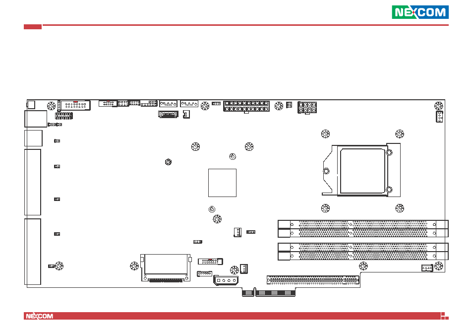
Locations of the Jumpers and Connectors
NSB 5130
The figure on the right is the NSB 5130 main board which is the main board used in the NSA 5130 system. It shows the locations of the jumpers and connec-
tors.
CPU
PCH C206
LAN1
SW1
JP2
CN2
JP1 J6
J7
CN1
J2
CON1
J3
CON2
J4
J5
J1
CN3
J8
J9
J10
JP3
J12
J13
J11
J14
JP4
CN6
JP6
FAN4
CN7
J18
CN4
VJP1
FAN1
JP5
FAN2
CN5
J16
J17
GFM1
PCIE1
DIMM1
DIMM2
DIMM3
DIMM4
FAN3
Advertising
See also other documents in the category NEXCOM Hardware:
- EBC 352 (68 pages)
- EBC 353 (62 pages)
- EBC 355 (63 pages)
- EBC 354 (63 pages)
- ICES 268 (96 pages)
- ICES 667 (100 pages)
- ICES 254 (98 pages)
- NEX 604 (61 pages)
- NEX 608 (67 pages)
- ICES 668 (105 pages)
- NEX 607 (75 pages)
- NEX 609 (61 pages)
- NEX 611 (51 pages)
- NEX 613 (45 pages)
- NEX 617 (53 pages)
- NISE 101 (79 pages)
- NISE 104 (78 pages)
- NISE 2020 (84 pages)
- NISE 105A (78 pages)
- NISE 103 (83 pages)
- NISE 2110A (87 pages)
- NISE 2420 (84 pages)
- NISE 301 (74 pages)
- NISE 2310E (107 pages)
- NISE 2210E (110 pages)
- NISE 3100eP2 (75 pages)
- NISE 300 (95 pages)
- NISE 3140P2E (88 pages)
- NISE 3520P2E (125 pages)
- MAC 3500P2-GTS8 (120 pages)
- NISE 3600E (102 pages)
- NISE 3720P2E (85 pages)
- NISE 3640P2E (105 pages)
- NISE 3640M2E (108 pages)
- NISE 4000 (102 pages)
- nTUF 600 (100 pages)
- NEX 716VL2G (71 pages)
- NISE 4000P4E (128 pages)
- NISE 4000P2E (131 pages)
- NEX 732L2G (71 pages)
- NEX 883 (53 pages)
- NEX 890 (58 pages)
- NEX 980 (52 pages)
- NEX 852VL2 (62 pages)
- NEX 981 (47 pages)