Paxton Superchargers Mustang Novi 2000 User Manual
Page 16
3-4
P/N: 4809610
©2003 Paxton Automotive
All Rights Reserved, Intl. Copr. Secured
05DEC03 v2.0 MusGT(4809610 v2.0)
Fig. 3-j
Fig. 3-k
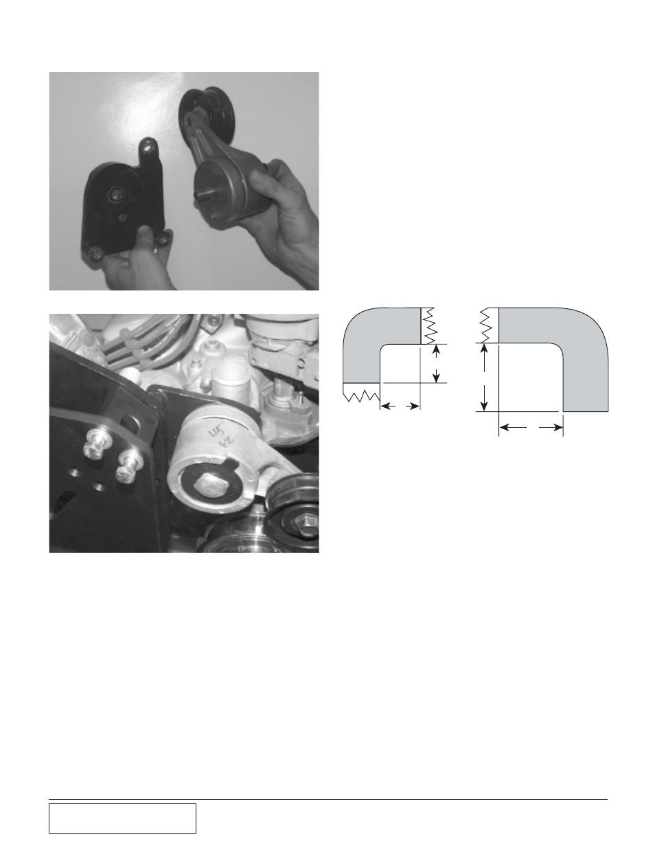
Fig. 3-l
U.
Install the new fan spacer on the water
pump. Place the fan and shroud back into
the engine compartment together. Re-install
the factory fan and clutch using the 5/16"
bolts and washers. Tighten with a 1/2"
wrench to the factory specifications. Use
the factory screws to re-install the shroud
onto the radiator core support.
V.
Use an 18mm wrench to rotate the accessory
belt tensioner and reinstall the factory belt in
the correct routing. (See Appendix C.)
W. Install the supercharger drive belt between
the crank pulley and the supercharger pulley.
Route the belt inside the idlers. Use a 3/8"
socket and extension and tighten the belt.
Once the belt is tensioned, tighten the nut on
the end of the adjustable idler so that it will
not back off.
X.
Find the rubber air injection hose from the
diverter valve removed in an earlier step.
Shorten the hose by cutting 3" out of the
middle of the hose and 1-1/2" off the back
end of the hose. Reconnect the two formed
pieces together with the sleeve and clamps
provided. Re-install the short end hose
between the diverter valve and fitting on the
side of the smog pump.
Y.
Cut the upper radiator hose. Re-install the
longer piece on the thermostat housing
angled forward. Install the shorter 90º
degree piece on the radiator angled to the
side. Install the stainless tube between the
two pieces of hose and secure with the sup-
plied clamps. (See Fig. 3-l.)
Z.
Remove the vent tube from the throttle body
and the oil fill cap and clamp, plug the nip-
ple on the throttle body with a nipple plug
and using a hose clamp securely retain the
nipple cover.
AA. Install the intake u-bend with the supplied 3
1/2" x 4" adapter sleeve and clamps. On the
other end of the U-bend, install the 3 1/2" x
3 1/4" adapter sleeve. (See Appendix E.)
BB. Plug in the Mass air flow (MAF) sensor and
install the sensor into the opposite side of
the adapter sleeve with the supplied clamps.
(see Appendix E)
CC. Install the K&N air filter on the end of the
MAF sensor. Tighten the clamp to secure the
filter. (See Appendix E.)
DD. Install the brass fitting into the hole in the
front of the filter cover and tighten. Place
the filter cover over the filter and secure it to
the inner fender with the supplied screws.
Install the supplied crankcase breather hose
on this nipple and route it back to the oil
filler cap. Trim to fit and install this end of
the hose to the nipple on the side of the oil
fill spout clamp to secure.
2"
2"
3"
3"