Paxton Superchargers Plymouth Prowler User Manual
Page 29
11-3
P/N: 4809629
©2003 Paxton Automotive
All Rights Reserved, Intl. Copr. Secured
22OCT02 v2.0 PlymProwler(4809629v2.0)
Fig. 11-4
M. Ground to the relay is supplied by the black
wire running from a screw in the frame rail
under the fuse box on the driver’s side. (See
Fig. 11-5.) This wire is attached to the screw
on the frame rail with a ring connector and
to the relay with a female disconnect on the
85 terminal (relay).
Fig. 11-5
L.
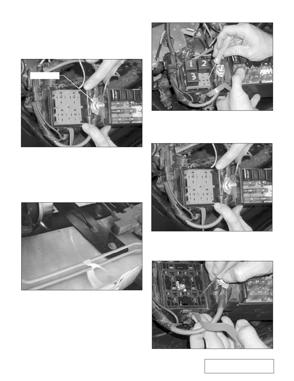
Power to the relay is supplied by a red wire,
running from the positive (red) terminal on the
fuse box. (See Fig. 11-4.) This wire is attached
to the fuse box with the 3/8” ring connector
and to the relay with a female disconnect on
the 30 terminal relay.
N.
Open the Fuse box and find connection #16.
Take the time to number the other connec-
tors for identification to help in the reassem-
bly. (See Fig. 11-6.)
Fig. 11-6
O.
Remove the plugs, and remove the red plas-
tic relay port by pressing on the tabs in the
corners. (See Fig. 11-7.)
Fig. 11-7
RELAY POWER
P.
Detach the wire to the connector by pressing
on it from the top side with a small screw-
driver. (See Fig. 11-8.)
Fig. 11-8