3 trap interrupt – Zilog Z80380 User Manual
Page 218
6-4
Z380
™
U
SER
'
S
M
ANUAL
DC-8297-03
Z
ILOG
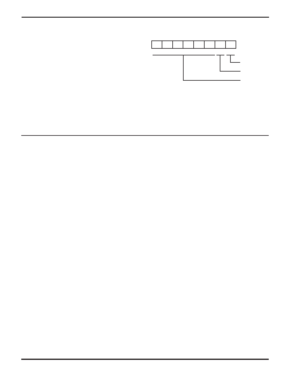
6.2.2.5 Trap and Break Register
D7-D2 Reserved. Some of these bits are reserved for
development support functions. Read as 0, should write to
as 0.
D1 TF (Trap on Instruction Fetch). TF goes active to logic
1 when an undefined opcode fetched in the instruction
stream is detected. TF can be reset under program control
by writing it with a logic 0. However, it cannot be written with
a logic 1.
D0 TV (Trap on Interrupt Vector). TV goes active to logic 1
when an undefined opcode is returned as a vector in an
Interrupt acknowledge transaction in mode 0. TV can be
reset under program control by writing it with a logic 0.
However, it cannot be written with a logic 1 (See Figure
6-3).
7
TF
TV
0
0
0
0
0
0
0
0
0
Reset Value
TRPBK: 00000019H
R/W
Trap on
Interrupt Vector
Reserved
Program as 0
Read as 0
--
--
--
--
Trap on
Instruction Fetch
--
--
Figure 6-3. Trap and Break Register
6.3 TRAP INTERRUPT
The Z380 MPU generates a Trap when an undefined
opcode is encountered. The Trap is enabled immediately
after reset, and it is not maskable. This feature can be used
to increase software reliability or to implement “extended”
instructions. An undefined opcode can be fetched from
the instruction stream, or it can be returned as a vector in
an Interrupt acknowledge transaction in Interrupt Mode 0.
When a Trap occurs, the Z380 MPU operates as follows.
1.
The TF or TV bit in the Assigned Vectors Base and Trap
Register goes active, to indicate the source of the
undefined opcode.
2.
If the undefined opcode was fetched from the instruc-
tion stream, the starting address of the Trap causing
the instruction is pushed onto the stack. (Note that the
starting address of decoder directive(s) preceding an
instruction encoding is considered the starting ad-
dress of the instruction.)
If the undefined opcode was a returned Interrupt vector,
the interrupted PC value is pushed onto the stack.
3.
The states of IEF1 and IEF2 are cleared.
4.
The Z380 MPU commences to fetch and execute
instructions from address 00000000H.
Note that instruction execution resumes at address 0,
similar to the occurrence of a reset. Testing the TF and TV
bits in the Assigned Vectors Base and Trap Register will
distinguish the two events. Even if Trap handling is not in
place, repeated restarts from address 0 is an indicator of
possible illegal instructions at system debugging.