And table 2-2, Table 2-3 – AMETEK ASD Series User Manual
Page 28
Installation
Sorensen ASD Series
2-30
M551177-01 Rev A
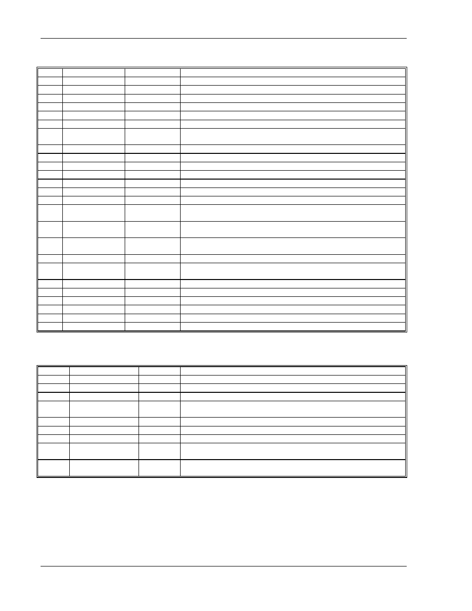
Table 2-2. Analog Interface Signals. SG-compatible Pin-out (DB25)
PIN #
PIN NAME
IN/OUT
DESCRIPTION
1
Not used.
2
Not used.
3
Not used.
4
GND
common
5
ON/OFF
D/IN
LO = 0 VDC enables output, HI > 8 VDC disables output.
6
GND
common
7
I_MON
A/OUT
a 0-10 VDC monitor signal (or 4-20 mADC) that indicates zero to full
scale output current. (Zout ~ 10 ohms for voltage signal)
8
Not used.
9
Not used.
10
Not used.
11
Not used.
12
Not used.
13
Not used.
14
Not used.
15
V_PROG
A/IN
a 0-10 VDC analog input signal (or 4-20 mADC) that programs zero to
full scale output voltage. (Zin ~ 200 Kohms for voltage signal)
16
I_PROG
A/IN
a 0-10 VDC analog input signal (or 4-20 mADC) that programs zero to
full scale output current. (Zin ~ 200 Kohms for voltage signal)
17
FAULT
D/OUT
LO = 0 VDC indicates normal operation, HI = 12 VDC indicates a fault.
See Table 4-11 for a list of faults and their description.
18
Not used.
19
V_MON
A/OUT
a 0-10 VDC monitor signal (or 4-20 mADC) that indicates zero to full
scale output voltage. (Zout ~ 10 ohms for voltage signal)
20
GND
common
21
Not used.
22
Not used.
23
GND
common
24
GND
common
25
GND
common
Table 2-3. Pin-out of the Reduced Analog Interface Connector (DB9)
PIN #
PIN NAME
IN/OUT
DESCRIPTION
1
RS-485 A
D/IO
Modbus-RTU interface
2
START/STOP
D/IN (**)
LO disables output, HI enables output.
3
+24Vdc
OUT
+24VDC output, 100mA max
4
I_PROG
A/IN
a 0-10 VDC analog input signal (or 4-20 mADC) that programs zero to
full scale output current
5
GND
-
ground
6
RS-485 B
D/IO
Modbus-RTU interface
7
STATUS
D/OUT
LO indicates output disabled, HI indicates the output is enabled.
8
V_MODE
D/OUT
LO indicates the unit is not in voltage mode, HI indicates the unit is in
voltage mode.
9
V_PROG
A/IN
a 0-10 VDC analog input signal (or 4-20 mADC) that programs zero to
full scale output voltage