AMETEK HPD Series User Manual
Page 19
Installation and Configuration
Initial Inspection
17
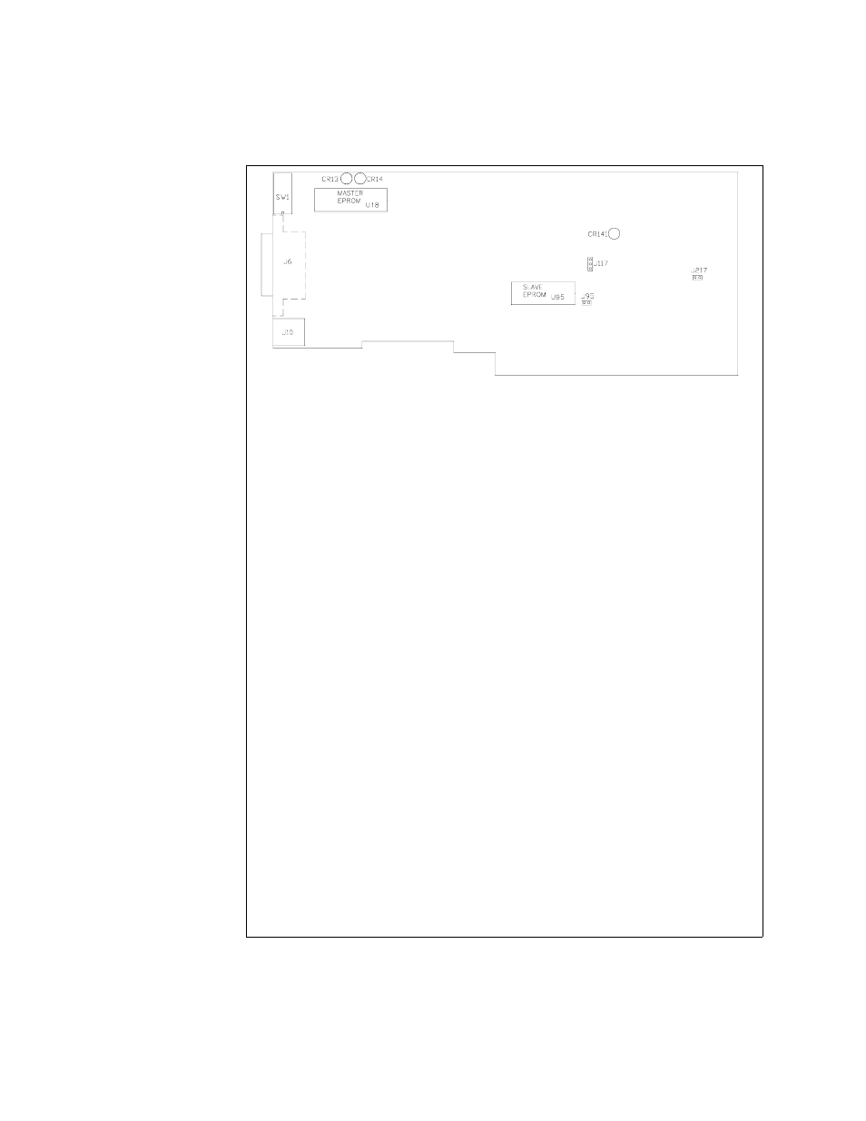
Figure 2.3 GPIB Interface PCB
JUMPER SELECTION
J217
Local OVP control selection
[closed] [default]. See page 19.
[open] Front Panel OVP Control.
J117
User TTL shutdown (S/D) selection
[1-2] User TTL S/D line active low.
See page 26.
[2-3] [default] User TTL S/D line active high.
J217
Local Mode Disable Selection
[closed] [default]. See page 23.
[open] Software control of power supply only
Note: All other jumpers are not user-selectable.
LED INDICATORS
CR141
Red Diagnostic LED
Bus error or soft restart on Slave circuitry.
CR14
Red Diagnostic LED
Soft restart on Master circuitry.
CR13
Green Diagnostic LED
Bus error on Master circuitry.
EPROMS
U958
Slave EPROM
See revision number stamped on EPROM.
U18
Master EPROM
See revision number stamped on EPROM.
CONNECTORS
J6
IEEE 488 Bus Connector (J8 on rear panel subplate)
J10
User Signal Connector (J7 on rear panel subplate)