Input – AMETEK PLA-PLW User Manual
Page 52
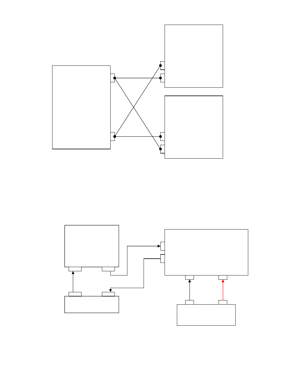
PARALLEL CONFIGURATION
TRIGGER OPERATION
Figure depicts the method of triggering the
Eectronic Loads. The TRIGOUT signal of the
Electronic Load is
connected to the Trigger input of the DMM. Additional instruments can be daisy chained to a DMM in the same manner.
Once the preset settings of the instruments have been programmed, one trigger signal can simultaneously set all
instruments to their transient settings.
Note: Trigger Operation is Negative-Edge Triggered
TRIGGER CONFIGURATION
(-)
(+)
DC Power Supply
+
_
PROGRAMMING
ELECTRONIC
LOAD
–
+
PROGRAMMING
ELECTRONIC
LOAD
–
+
(+)
(-)
– +
DEVICE UNDER TEST
OSCILLOSCOPE
XT in XT out
XT out XT in
DMM
Programming Electronic Load
(Trig-in) Pin – 10 at External Programming Port
(Trig-out) Pin – 11 at External Programming Port
– Input +
2-12