Aplex Technology APC-3218 User Manual
Page 23
APC-3X18 User Manual
23
Procedures of CMOS clear:
a) Turn off the system and unplug the power cord from the power outlet.
b) To clear the CMOS settings, use the jumper cap to close pins1 and 2 for about
3 seconds then reinstall the jumper clip back to pins open.
c) Power on the system again.
d) When entering the POST screen, press the <F1> or <DEL> key to enter CMOS
Setup Utility to load optimal defaults.
e) After the above operations, save changes and exit BIOS Setup.
3. BAT1 :
(1.25mm Pitch 1X2 box Pin Header) 3.0V Li battery is embedded to provide
power for CMOS.
Pin#
Signal Name
Pin1
VBAT
PIN2
Ground
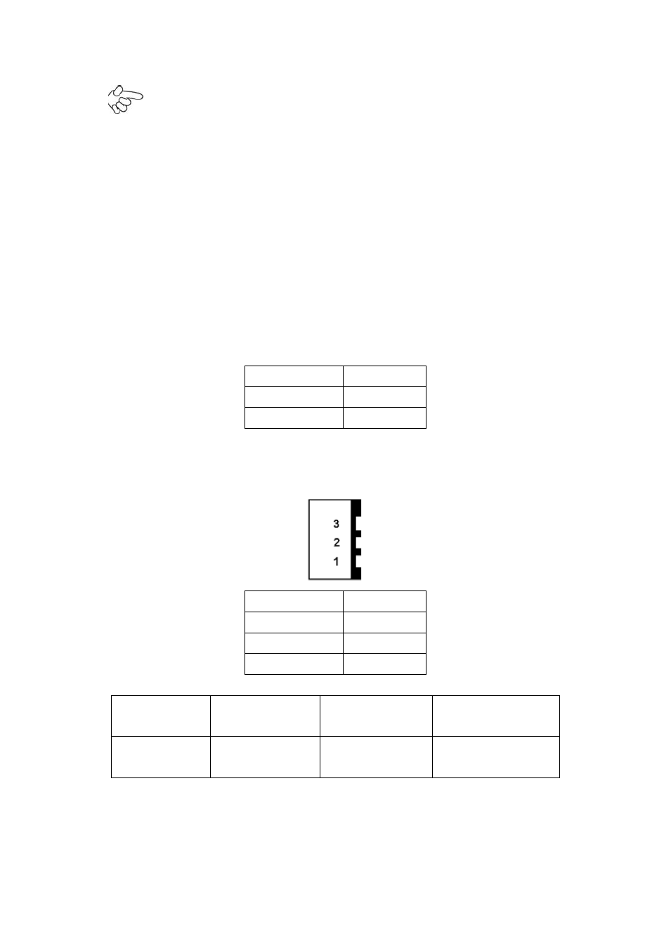
4. DCIN:
(5.08mm Pitch 1x3 Pin Connector),DC9V ~ DC32V System power input connector.
Pin#
Power Input
Pin1
DC+9V~32V
Pin2
Ground
Pin3
PG
Power Mode
Location: DCIN
(5.4.4.)
Location: ATX12V
(5.4.5.)
Location: ATX
(5.4.6.)
AT
(Default)
input
DC9~32V
output
DC 12V
NC
5. ATX12V:
(2x2 Pin Connector),DC12V System power
output
connector.