Aplex Technology APC-3218 User Manual
Page 36
Advertising
APC-3X18 User Manual
36
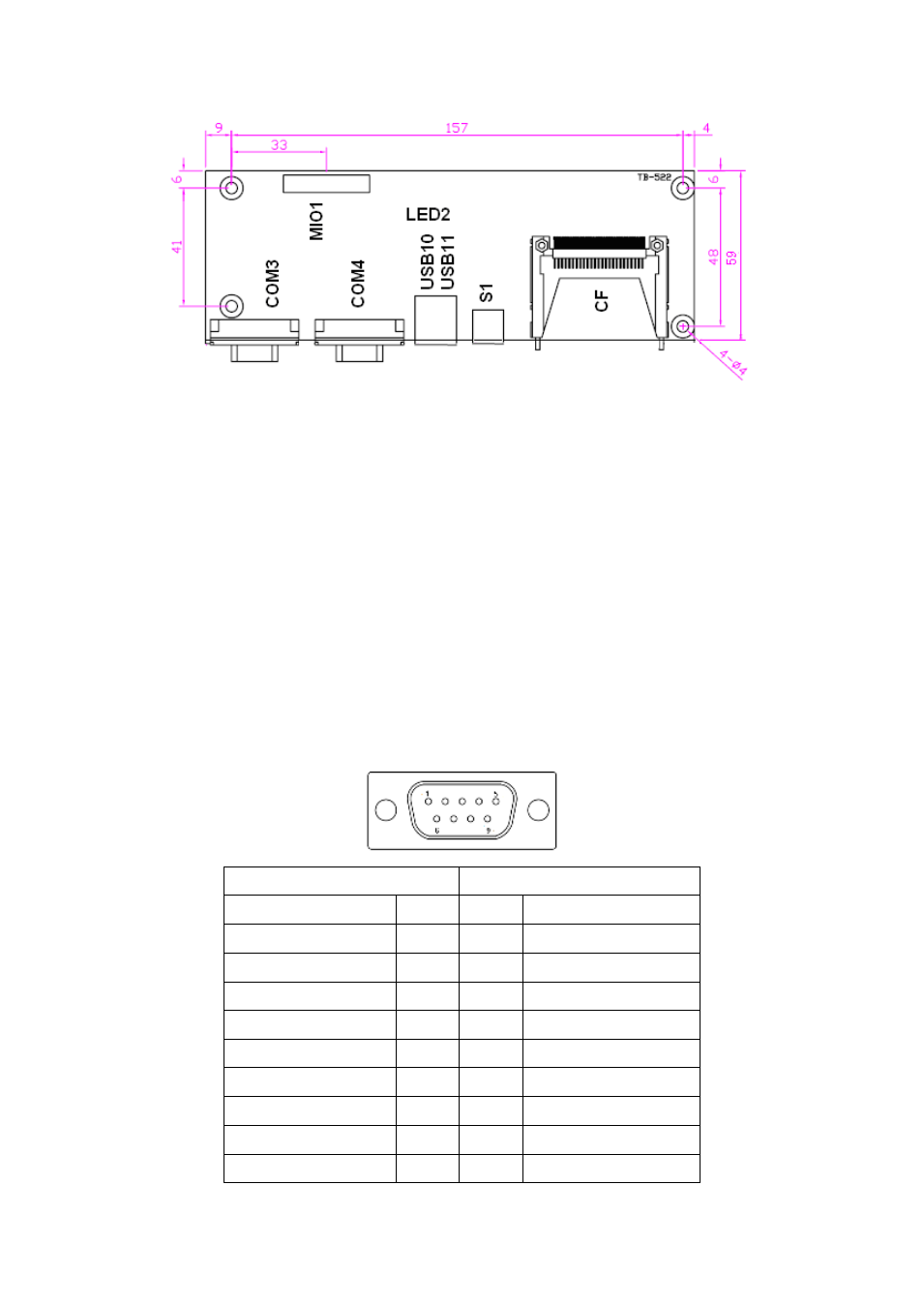
LED2:
CF Card LED Status.
S1:
PWR BT: POWER on/off Button, They are used to connect power switch button.
The two pins are disconnected under normal condition. You may short them
temporarily to realize system startup & shutdown or awaken the system from
sleep state.
PWR LED: POWER LED status.
COM3:
(Type DB9), I/O serial port, it provides selectable RS422/RS485 serial signal
output.
RS422 Type (option)
RS485 Type (option)
Signal Name
Pin#
Pin#
Signal Name
422_RX+
1
1
NC
422_RX-
2
2
NC
422_TX-
3
3
485-
422_TX+
4
4
485+
Ground
5
5
Ground
NC
6
6
NC
NC
7
7
NC
NC
8
8
NC
NC
9
9
NC
Advertising