Aplex Technology APC-3218 User Manual
Page 42
APC-3X18 User Manual
42
PWR BT: POWER on/off Button, they are used to connect power switch button.
The two pins are disconnected under normal condition. You may short them
temporarily to realize system startup & shutdown or awaken the system from
sleep state.
PWR LED: POWER LED status.
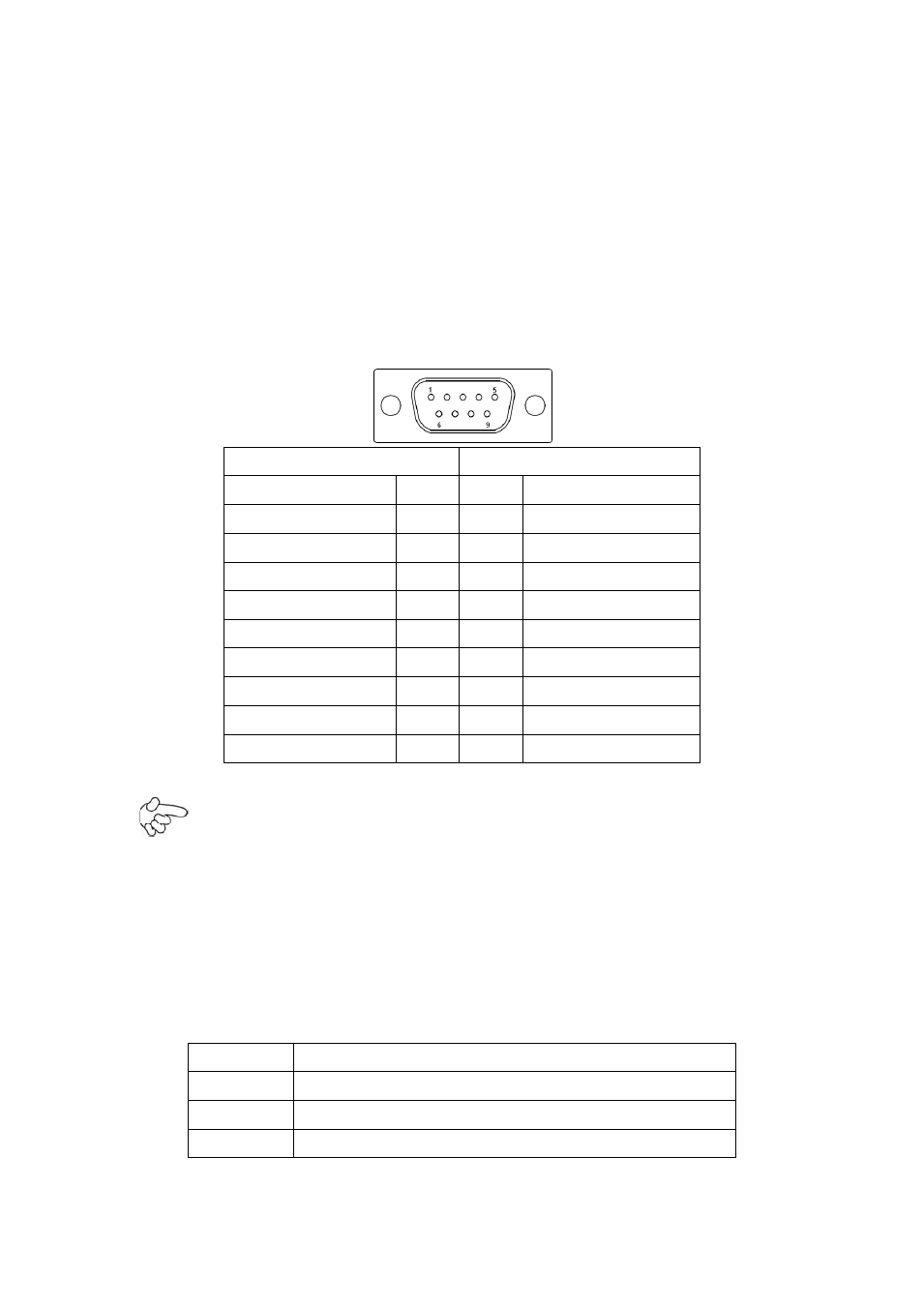
COM3:
(Type DB9), I/O serial port, it provides selectable RS422/RS485 serial signal
output.
RS422 Type (option)
RS485 Type (option)
Signal Name
Pin#
Pin#
Signal Name
422_RX+
1
1
NC
422_RX-
2
2
NC
422_TX-
3
3
485-
422_TX+
4
4
485+
Ground
5
5
Ground
NC
6
6
NC
NC
7
7
NC
NC
8
8
NC
NC
9
9
NC
Note:
Use COM3 RS422 or RS485 Function, please enter BIOS CMOS Setup. Path:
BIOS Setup Utility \ Advanced /Super IO Configuration \ Serial Port3 Type:
[RS-485]
[RS-422]
JP4:
(2.0mm Pitch 2x10 Pin Header) COM4 function setting jumper.
Function
JP4 Pin#
RS232
Close: 3-5, 4-6, 10-12, 11-13 (Default)
RS422
Close: 1-3, 2-4, 5-7, 8-10, 9-11, 12-14, 18-20 (option)
RS485
Close: 5-7, 8-10, 9-11, 12-14, 16-18 (option)