Setting and parameterisation of the modbus – BECKHOFF BC7300 User Manual
Page 24
MODBUS
24
BC7300
Setting and Parameterisation of the
MODBUS
The MODBUS is parameterised by means of the rotary switch on the
BC7300. Only the Bus Terminal Controller's end terminal may be inserted
for this.
Only plug the KL9010 into the BC7300. Use the rotary switch to select the
parameters. The x10 address switch is used to select the parameter, while
the x1 address switch is used for the associated setting. The settings can
be found in the table. Connect the Bus Coupler's 24 V supply, and the
Modbus coupler will now start up in parameterisation mode. The LEDs WD,
RX, TX and ERROR are now toggled, and the LEDs I/O RUN and I/O ERR
give the function value.
You want to check whether the correct baud rate has been set.
1.
Switch off the Bus Coupler's 24 V supply
2.
Remove all the terminals except the KL9010 end terminal
3.
Set the x10 address selection switch to 0 and the x1 switch to 3
4.
Switch on the Bus Coupler's 24 V supply again
The coupler indicates the set baud rate via the LEDs.
3 x flashes of the I/O RUN and I/O ERR LEDs means 9600 baud
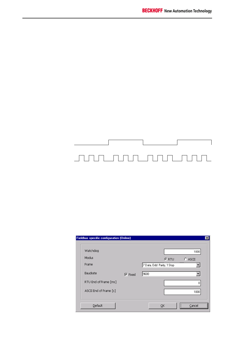
WD,RX,TX,ERROR LEDs
1 2 3 1 2 3 1 2 3 1 2 3
Example
I/O Run, I/O ERR
Now you want to set a new rate of 1200 baud
5.
Switch off the Bus Coupler's 24 V supply
6.
Set the x10 address selection switch to 3 and the x1 switch to 6
7.
Switch on the Bus Coupler's 24 V supply again
The Bus Coupler indicates the new set baud rate via the LEDs.
6 x flashes of the I/O RUN and I/O ERR LEDs means 1200 baud
Incorrect Entry
If a parameter is set that the MODBUS Bus Terminal Controller does not
recognise, this is indicated by a constant even flashing of the I/O RUN and
I/O ERR LEDs, while all the other LEDs remain off.
KS2000
The parameter settings can also be carried out with the KS2000 software.