Example program, Explanation of the program, The program in the bus terminal controller – BECKHOFF BC7300 User Manual
Page 43
Appendix
BC7300
43
Example Program
This example program makes use of the basic settings for the BC7300.
This makes it very easy to quickly include this Bus Terminal Controller in
the data exchange for the first time. The procedure is explained step by
step with the aid of a small example.
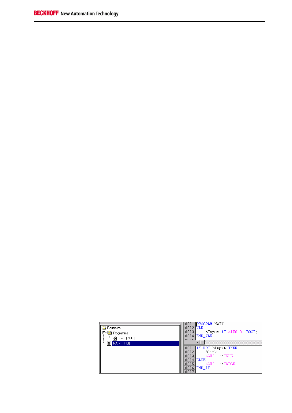
Explanation of the Program
The following very simple example should clarify the function and type of
data transmission with the aid of the PLC variables. The blinker block is
called in the MAIN program when the first input of the input terminal has
reached the value zero. The blinker block contains a pulse generator that is
fed to two counters. One of the counters increments output word 130, while
the other counts output word 128 downwards. Both of these output words
are what are known as PLC variables, and they are read by the MODBUS
master.
The Program in the Bus Terminal Controller
In order to generate this example program you need a BC7300, 2 x
KL2012, 2 x KL1002, 1 x KL9010 and a 24V DC mains power supply unit
(2A) with a cable and a connection on your MODBUS master to the
BC7300. The software you require is TwinCAT / TwinCAT BC and a
programming cable. This is included when TwinCAT BC or KS2000 is
supplied.
The first step is to create a program in the BC7300. For this purpose the
address selection switch is set to "00". This it the programming mode for
the Bus Terminal Controller. The MODBUS cannot be operated at the
same time, which means that the fieldbus connection must not be
connected. Connect the supply voltage and the supply to the power
contacts. The Bus Terminal Controller now boots. When booting is
complete the "I/O RUN" LED lights up on the BC7300. Insert the
programming cable into your PC's serial interface and into the
programming interface of the BC7300. Open the flap under the Beckhoff
logo to do this. Start TwinCAT or TwinCAT BC, and under File/New select
the item "BC serial". Confirm with "OK". Then select "ST" as the language,
and confirm with "OK". Now test communication with the BC by executing a
reset under Online/Coupler/K-Bus reset. If a message box then appears
with the number of Bus Terminals inserted (not counting the end terminal),
the communication has been successful. If, after about 15 seconds, a
"Communication error" message appears, check the cable, the address on
the BC7300 and the settings of the serial interface. You will find these
under Online/Communication parameters. The necessary setting is 19200
baud, 1 start bit, even parity.
Example program on the
BC7300
MAIN block (PRG-ST)