Functions, Read digital outputs (function 1) – BECKHOFF BC7300 User Manual
Page 27
BC7300
27
Functions
In the MODBUS protocol, the functions determine whether data are to be
read or written, and what kind of data is involved. In the ASCII protocol the
fourth and fifth bytes are function bytes, while in the RTU protocol it is the
second byte.
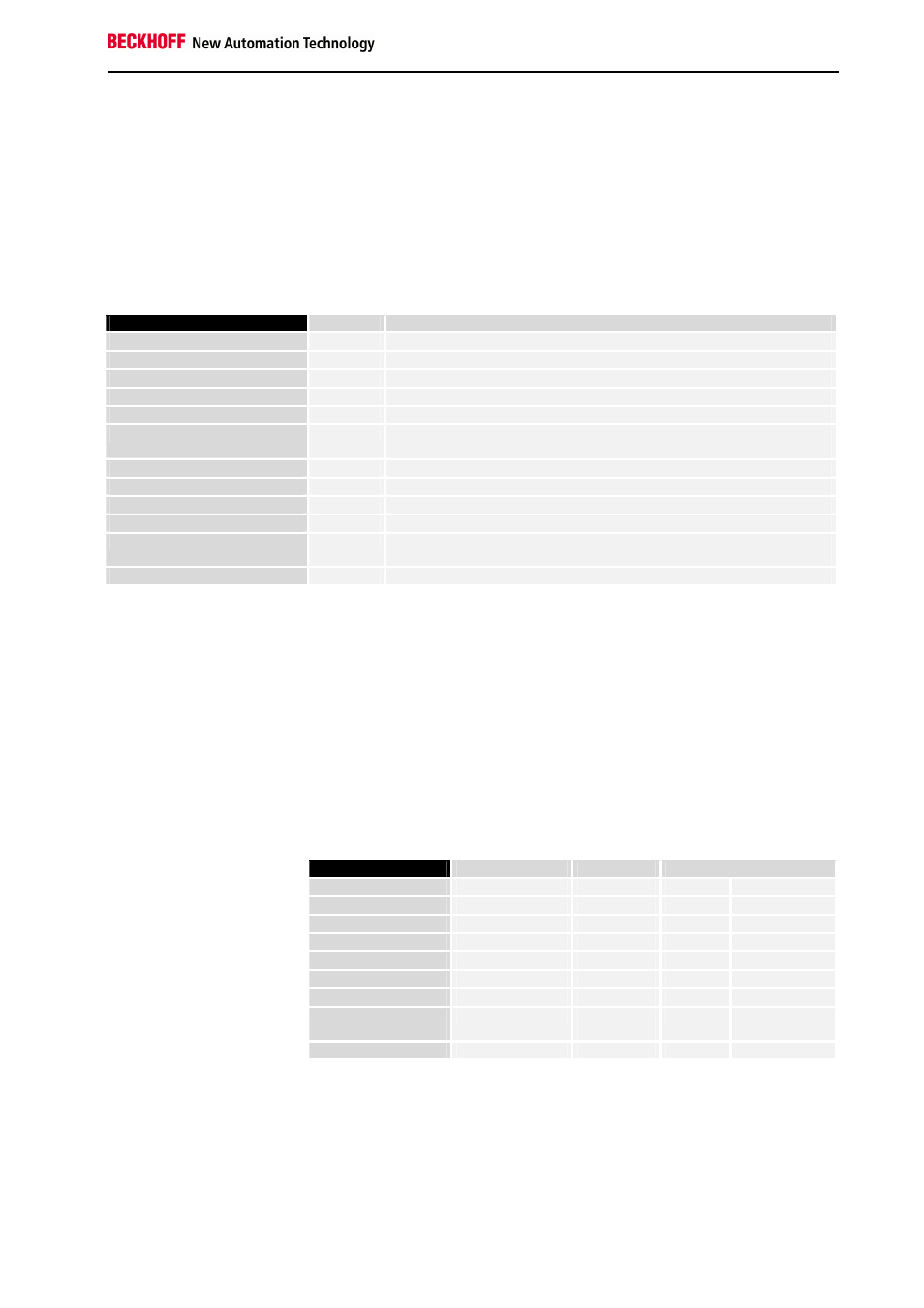
The Beckhoff MODBUS Bus Terminal Controller supports the following
functions:
Function
Code
Description
Read coil status 1
Read digital outputs
Read input status 2
Read digital inputs
Read holding registers 3
Read analog outputs / GPR
Read input registers 4
Read analog inputs / GPR
Force single coil 5
Write one digital output
Preset single register 6
Write one analog output /
GPR
Diagnostics 8
Read the MODBUS diagnostic register
Force multiple coils 15
Write a number of digital outputs
Preset multiple registers 16
Write a number of analog
outputs / GPR
Read / Write Registers 23
Write and read a number of process data outputs / GPRs
GPR – General Preset Register (see Modbus Interface)
The functions are briefly described in the next section and clarified with the
aid of an example.
Read Digital Outputs (Function 1)
READ COIL STATUS
Function 1 can be used to read the settings of the digital outputs.
In this example the first 10 digital outputs of slave number 11 are read. The
start address is zero. If an offset is to be entered, this is done in the "Start
address" field.
Query
Byte Name
Example
RTU
ASCII
Start frame
„:“
0x3A
Slave address 11
0x0B
„0B“
0x30, 0x42
Function code 1
0x01
„01“
0x30, 0x31
Start address high 0
0x00
„00“
0x30, 0x30
Start address low 0
0x00
„00“
0x30, 0x30
Count high 0
0x00
„00“
0x30, 0x30
Count low 10
0x0A
„10“
0x31, 0x30
Error Check
LRC / CRC
0xBC
0xA7
„E4“
0x45, 0x34
End of frame
t1-t2-t3
CRLF
0xD, 0xA
Response
The Bus Terminal Controller answers with byte count 2, i.e. 2 bytes of data
are returned. The query was for 10 bits, and these are now distributed over
2 bytes. The third bit in the output process image of the BC7300 is set, and
the Bus Coupler returns a "4" in the first data byte.