Writing a digital output (function 5), Writing an analog output (function 6) – BECKHOFF BC7300 User Manual
Page 30
MODBUS
30
BC7300
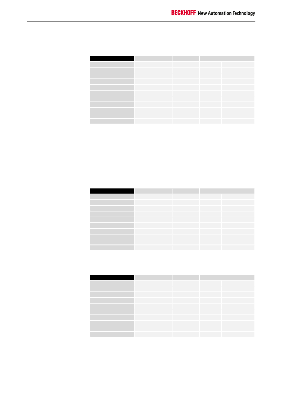
distributed over 2 words. In the analog input process image, the first
channel has the value 0x0038, while the second channel has the value
0x3F1B.
Byte Name
Example
RTU
ASCII
Start frame
„:“
0x3A
Slave address 11
0x0B
„0B“
0x30, 0x42
Function code 4
0x04
„04“
0x30, 0x34
Count byte 4
0x04
„04“
0x30, 0x30
Data 1 high byte 0
0x00
„00“
0x30, 0x30
Data 1 low byte 56
0x38
„38“
0x33, 0x38
Data 2 high byte 63
0x3F
„3F“
0x33, 0x46
Data 2 low byte 11
0x0B
„0B“
0x30, 0x42
Error Check
LRC / CRC
0x80
0x7E
„6A“
0x36, 0x41
End of frame
t1-t2-t3
CRLF
0xD, 0xA
Writing a Digital Output (Function 5)
FORCE SINGLE COIL
Function 5 can be used to write a digital output. In this example the third
digital output of slave number 11 is written. The digital outputs begin at
offset 0x0000 (hex). The digital value is located in the high byte of the data.
To switch the output on, "Data high" must contain 0xFF (hex), while 0x00
(hex) is used to switch the output off again. "Data low" must contain 0x00
(hex).
Query
Byte Name
Example
RTU
ASCII
Start frame
„:“
0x3A
Slave address 11
0x0B
„0B“
0x30, 0x42
Function code 5
0x05
„05“
0x30, 0x35
Start address high 0
0x00
„00“
0x30, 0x30
Start address low 2
0x02
„02“
0x30, 0x32
Data high 255
0xFF
„FF“
0x46, 0x46
Data low 0
0x00
„00“
0x30, 0x32
Error Check
LRC / CRC
0x2D
0x50
„EF“
0x45, 0x46
End of frame
t1-t2-t3
CRLF
0xD, 0xA
Response
The Bus Terminal Controller answers with the same telegram.
Byte Name
Example
RTU
ASCII
Start frame
„:“
0x3A
Slave address 11
0x0B
„0B“
0x30, 0x42
Function code 5
0x05
„05“
0x30, 0x35
Start address high 0
0x00
„00“
0x30, 0x30
Start address low 2
0x02
„02“
0x30, 0x32
Data high 255
0xFF
„FF“
0x46, 0x46
Data low 0
0x00
„00“
0x30, 0x32
Error Check
LRC / CRC
0x2D
0x50
„EF“
0x45, 0x46
End of frame
t1-t2-t3
CRLF
0xD, 0xA
Writing an Analog Output (Function 6)
PRESET SINGLE
REGISTER
Function 6 can be used to access the output process image and the
interface.
The first analog output of slave number 11 is written with function 6. The
analog outputs begin at offset 0x0800 (hex). Here again the offset always
describes a word. This means offset 0x0803 refers to the fourth word in the
output process image.