The interfaces, Electrical power supply, Power contacts feeding points – BECKHOFF BC7300 User Manual
Page 9: Power contacts, Fieldbus connection
Basic Principles
BC7300
9
If data exchange over the fieldbus fails, the PLC task continues to run as
an autonomous system.
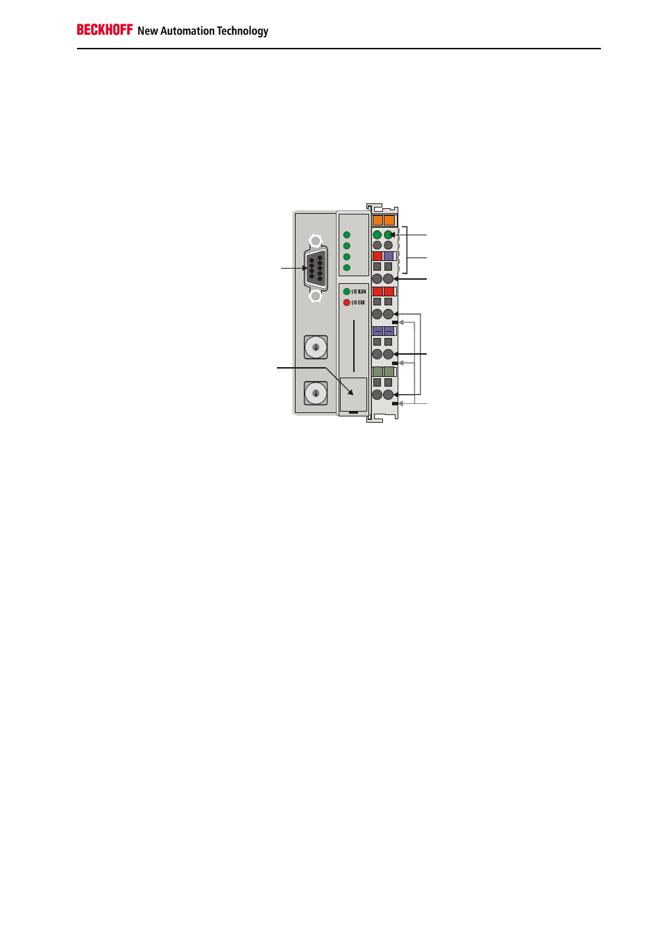
The interfaces
A Bus Terminal Controller has six different methods of connection. These
interfaces are designed as plug connectors and as spring-loaded terminals.
The MODBUS – Bus
Terminal Controller
BC7300
02
01
+ +
PE PE
WD
RX
TX
MODBUS
B
E
C
K
H
O
F
F
24V
0V
0
9
8
7
6
5
4
3
2
1
0
9
8
7
6
5
4
3
2
1
BC
7
30
0
Power LEDs
Bus Coupler / power contacts
K-Bus
MODBUS
Configuration and
programming
interface
Bus Coupler power supply
24 V DC / GND
Power contacts
feeding points
Power contacts
PLC
Electrical power supply
24 V DC to the topmost
terminals “24 V” and “0 V”
The Bus Terminal Controllers require a 24 V DC supply for their operation.
The connection is made by means of the upper spring-loaded terminals
labelled “24 V” and “0 V”. This supply voltage feeds not only the Bus
Coupler electronics via the K-Bus, but also the Bus Terminals. The power
supply for the Bus Coupler electronics and that of the K-Bus are electrically
separated from the potential of the field level.
Power contacts feeding points
Lower 3 terminal pairs for
power feed
Maximum 24 V
Maximum 10 A
The bottom six connections with spring-loaded terminals can be used to
feed the supply for the peripherals. The spring-loaded terminals are joined
in pairs to a power contact. The feed for the power contacts has no
connection to the voltage supply for the Bus Coupler. The design of the
feed permits voltages of up to 24 V. The assignment in pairs and the
electrical connection between feed terminal contacts allows the connection
wires to be looped through to various terminal points. The current drawn
from the power contact must not exceed 10 A for long periods. The current
rating between two spring-loaded terminals is identical to that of the
connecting wires.
Power contacts
Spring contacts on the side
On the right hand face of the Bus Terminal Controller there are three spring
contacts for the power contact connections. The spring contacts are hidden
in slots so that they can not be accidentally touched. By attaching a Bus
Terminal the blade contacts on the left hand side of the Bus Terminal are
connected to the spring contacts. The tongue and groove guides on the top
and bottom of the Bus Terminal Controllers and of the Bus Terminals
guarantees that the power contacts mate securely.
Fieldbus connection
9 pin sub-D socket strip
There is a recessed front face on the left hand side. The MODBUS
connection plug can be inserted here. A full description of the fieldbus
interfaces is found elsewhere in this manual. (In the section on The
Medium: Plugs and Cables)