BECKHOFF BC8000 User Manual
Page 17
BC8000
17
damage cannot be ruled out when devices are plugged together while live.
The occurrence of an error during ongoing operation does not immediately
trigger output of the error code via the LEDs. The bus coupler must be
requested to diagnose the bus terminals. The diagnostic request is
generated after switching on or at the request of the master.
Communication errors
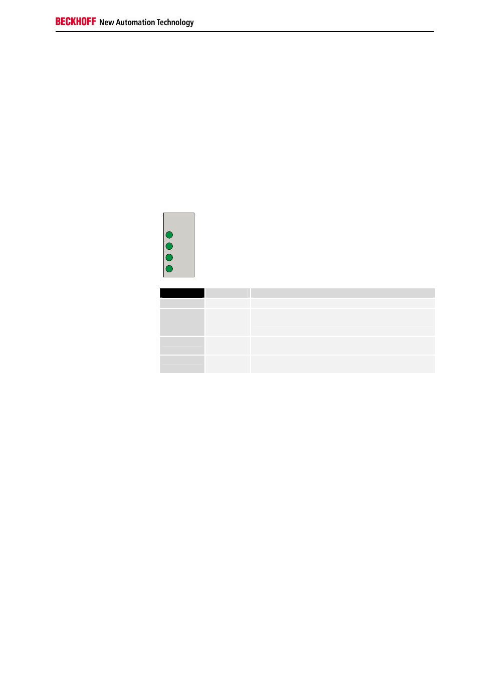
The top four LEDs show the operating states of RS485 communication.
The two bottom LEDs indicate local communication between the bus
coupler and bus terminals (as explained above).
The I/O RUN LED is controlled by the PLC in the synchronous state. The 3
communications LEDs indicate the state of the RS485 transmission. The
operating conditions are indicated by the „WD,“ „RX“ and „TX“ LEDs.
PLC-RUN
The green PLC LED on the bus terminal controller lights up when the PLC
task is in the RUN mode.
WD
RX
TX
PLC
RS485
LED
Operating state
WD
off
Controller operating as master.
RX
blinks,
flickers
The bus terminal controller is receiving data via the
interface.
TX
blinks,
flickers
The bus terminal controller is sending data over the
serial interface.
PLC
lights up,
blinks
PLC task is in RUN mode
Creating boot image
The green I/O LED lights up in connection with access to the internal K
bus. However, the bus coupler queries the configuration of the bus
terminals after switching on and does not exchange any data with the
terminals. That is to say, the red I/O LED goes off after an error-free
startup without the green I/O LED having to light up. Then, the green I/O
LED does not light up until data transfer is commenced (see above).