Appendix – BECKHOFF BC8000 User Manual
Page 25
Appendix
BC8000
25
Appendix
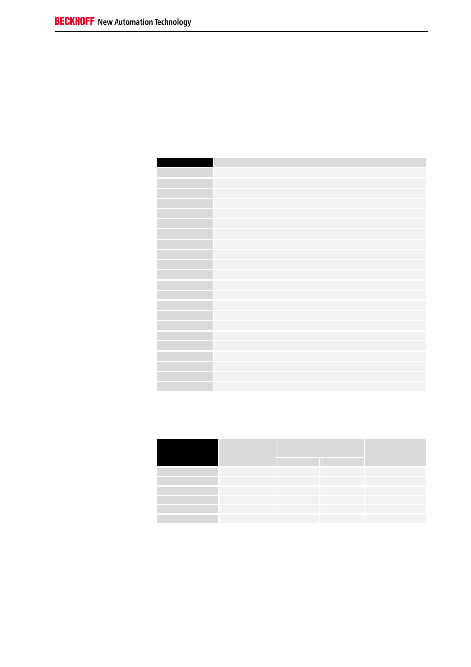
Example: Process image in the bus
terminal controller
An example shows the assignment of in- and output channels to the
process image. The sample construction should consist of the following
assembly of bus terminals:
Position
Functional groups on the rail
POS00
Bus terminal controller
POS01
Digital inputs, 2 channels
POS02
Digital inputs, 2 channels
POS03
Digital inputs, 2 channels
POS04
Digital inputs, 2 channels
POS05
Digital inputs, 2 channels
POS06
Digital inputs, 2 channels
POS07
Digital outputs, 2 channels
POS08
Digital outputs, 2 channels
POS09
Digital outputs, 2 channels
POS10
Analogue inputs, 2 channels
POS11
Analogue outputs, 2 channels
POS12
Analogue outputs, 2 channels
POS13
Analogue inputs, 2 channels
POS14
Power feed terminal
POS15
Digital inputs, 2 channels
POS16
Digital inputs, 2 channels
POS17
Digital inputs, 2 channels
POS18
Digital outputs, 2 channels
POS19
Analogue outputs, 2 channels
POS20
KL6001_0020 standard 5 bytes user data
With this configuration, the
bus terminal controller sets
up the following assignment
list
POS21
End terminal
In the BCXXXX bus terminal controllers, all terminals are always assigned
to the PLC, namely in complex evaluation with word alignment. In an
analogue terminal this means 4 input bytes and 4 output bytes per channel.
Controller
process
image
Relative byte
address
Bit position
Input
Output
Position
in
the block
0..7 none
%IB0..7
%QB0..7
POS10
8..15 none
%IB8..15
%QB8..15
POS11
16..23 none
%IB16..23
%QB16..23 POS12
24..31 none
%IB24..31
%QB24..31 POS13
32..39 none
%IB32..39
%QB32..39 POS19
Portion for byte-oriented
data
40..45 none
%IB40..45
%QB40..45 POS20