Periphery level, Bus terminals bus coupler field bus 24 v dc – BECKHOFF BC8000 User Manual
Page 9
Basic information
BC8000
9
RS 485 Connection
9 pole Sub-D female
connector strip
There is a recessed front surface on the left-hand side. A 9-pole Sub-D
connector can be plugged in here. A detailed description of the RS485
interface can be found in a further part of this manual (chapter entitled 'The
media: plugs and cable').
K-bus contacts
6 contacts at the side
The connections between the bus coupler and the bus terminals are
effected by gold contacts at the right-hand side of the bus coupler. When
the bus terminals are plugged together, these gold contacts automatically
complete the connection to the bus terminals. The K bus is responsible for
the power supply to the electronic components of the K bus in the bus
terminals, and for the exchange of data between the bus coupler and the
bus terminals. Part of the data exchange takes place via a ring structure
within the K bus. Disengaging the K bus, for example by pulling on one the
bus terminals, will break this circuit so that data can no longer be
exchanged. However, there are mechanisms in place which enable the bus
coupler to locate the interruption and report it.
Supply isolation
3 supply groups:
fieldbus
K-bus
peripheral level
The bus couplers operate with three independent supplies. The input
power supplies the electrically isolated K-bus circuitry in the bus coupler
and the K-bus itself. The power supply is also used to generate the
operating power for the fieldbus.
Note: All the bus terminals are electrically isolated from the K bus, so that
the K-bus is completely electrically isolated.
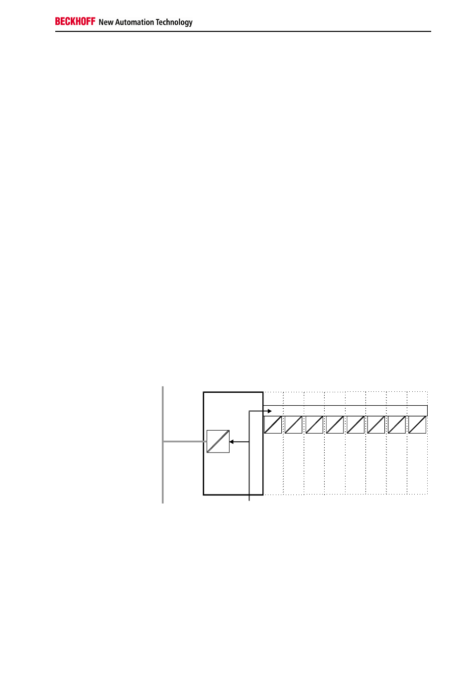
Setting up the power levels
in the bus terminal system
Periphery level
Bus terminals
Bus coupler
Field bus
24 V DC
Terminal bus