Installation, Hardware considerations power supply, Fuses and ratings – Cloud Electronics 36-50 User Manual
Page 12: System connections, Music sources, Hardware considerations, Power supply
36-50 Installation and User Guide V1.0
12
INSTALLATION
Hardware considerations
The 36-50 Mixing Amplifier is built in a 2U-high 19” rack
mount enclosure. It is recommended that the 36-50 is installed
in a 19” rack wherever possible. The units are approx. 300 mm
deep, but at least 400 mm of rack depth should be available to
allow for rear connectors and cabling.
The 36-50 uses convection cooling and there are no thermal
considerations other than ensuring that the ventilation grilles
are not obstructed once the Mixing Amplifier is installed. The
ventilation grilles are in the top and bottom panels, to the
right-hand side of the panels as viewed from the front. It is
recommended that 1U ventilation panels are fitted in the rack
above and below the 36-50.
If the unit is to be used free-standing (i.e., not mounted in
a rack), the four feet supplied in the accessory pack should
be fitted to the bottom of the unit to provide a satisfactory
airflow. Attach these with the M4 x 12 pan-head screws
provided; four M4 tapped holes are clearly identifiable in the
corners of the bottom panel.
Do not use any longer screws, as they may foul
internal components or wiring.
The choice of location will be dictated by the specifics of the
system and building layout. It is recommended that wherever
possible, the 36-50 should be mounted adjacent to as many
of the music sources (CD players, music servers, TV receiver
boxes, etc.) as practical.
When deciding the Mixing Amplifier’s location, bear in mind
that access to it (particularly the rear panel) will probably be
required even if a full complement of remote controls is being
fitted as part of the system, as certain adjustments can only
be made on the unit itself.
Power Supply
The European version of the 36-50
operates on standard 230V
AC mains; an alternative version is available which operates
on 115 V AC. An IEC mains cable with a plug appropriate for
each country is supplied with the European unit. The unit’s
power consumption is 112 VA (measured using pink noise, all
channels driven at 1/3-rated max. power into 4 ohms.)
Fuses and ratings
The only externally-accessible fuse is an AC mains fuse in
the IEC connector housing. Only replace a fuse with one of
exactly the same type. The table below gives the correct fuse
types.
VERSION RATING FUSE TYPE
230 V
3.15 A
20 mm x 5 mm slo-blo T3.15AH
115 V
6.3 A
20 mm x 5 mm slo-blo T6.3AH
The fuseholder may be accessed by prising the slide below the
connector open, using a small screwdriver. The holder has an
extra cavity for storing a spare fuse; note that the “active” fuse
is that in the inner cavity.
Internally, two 20mm x 5mm fast-blow F4.0A fuses protect
each amplifier channel (six in total). These are service
components, and should not require attention. Failure of any
of these fuses indicates a fault condition, which should be
immediately referred to a competent technician or authorised
service centre.
System connections
Music sources
Connect the system’s various music sources to
LINE 1 to
LINE
6. All line inputs offer unbalanced connection for stereo
sources on a pair of standard RCA jacks (phono sockets).
The sensitivity range available should allow most standard
items of audio equipment such as computers/tablets, music
servers and media receivers, etc., to operate at a satisfactory
level. Most equipment of this type will have stereo unbalanced
outputs, and as long as the source equipment is adjacent to
the Mixing Amplifier, normal phono-phono (or 3.5 mm jack-
to-phono) leads can be used. Always avoid using pre-made
leads of an unnecessary length.
Mono and stereo sources:
The mixing section of the 36-50 is mono; the stereo line inputs
are summed internally. Stereo sources should be connected
in a normal stereo configuration, using both L and R inputs. If
connecting a mono source with only a single output, it may be
connected to either the left or the right input.
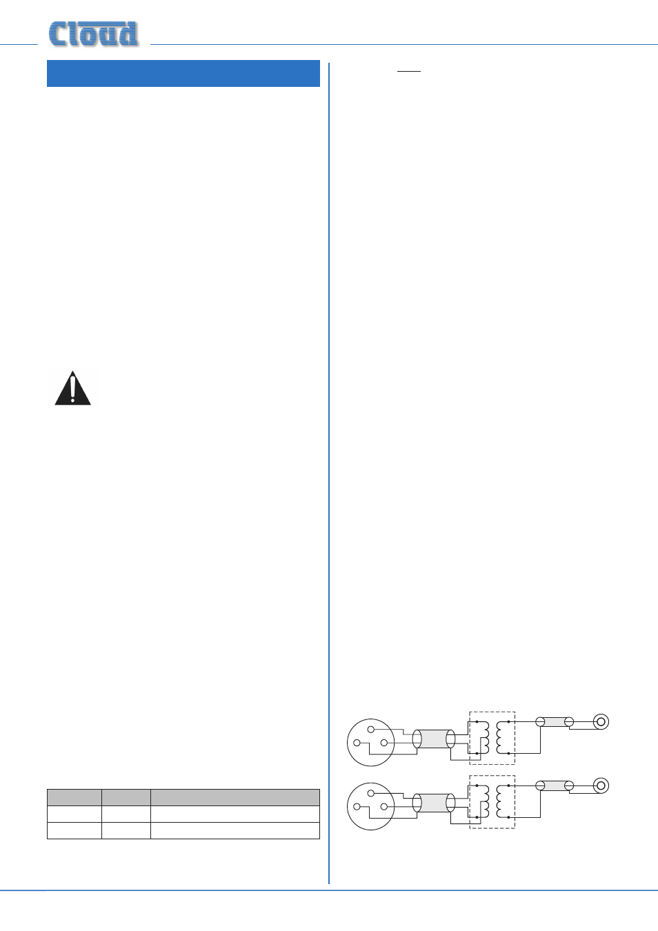
Balanced sources:
If it is necessary to connect an item of source equipment
with a balanced output to the 36-50, a balancing transformer
should ideally be inserted between the source and the
unbalanced input. Suitable audio transformers, which should
have a ratio of 1:1, are readily available from major audio
component suppliers. The transformer(s) should be mounted
as close to the 36-50 as practical, and housed in a screened
enclosure if they are not individually screened. The preferred
connection method is shown below.
LEFT
+
-
SCN
Unbalanced
inputs
SCN
LEFT
+
-
SCN
Audio balancing transformers
RIGHT
+
-
SCN
Unbalanced
inputs
SCN
RIGHT
+
-
SCN
pin 1 ground
pin 2 hot
pin 3 cold
Balanced outputs (XLRs):
1
2
3
1
2
3
If transformers are not available, a balanced source may feed
an unbalanced input directly as long as care is taken over how