Microphone input paging system connections, Microphone input, Paging system connections – Cloud Electronics 36-50 User Manual
Page 13: Connecting pm4/pm4-sa paging microphones
36-50 Installation and User Guide V1.0
13
the connections are made. A variety of design techniques are
in use to implement balanced outputs in audio equipment,
and some designs require different wiring protocols to others.
Installers are advised to check the manuals with each item
for guidance on how the outputs should be connected to an
unbalanced input.
However, the wiring methods shown below will work in a
large number of cases. If hum or other distortion is found to
result, try disconnecting the ‘cold’ leg of the balanced output
(pin 3 on XLRs).
1
2
3
Unbalanced
inputs
LEFT
RIGHT
+
+
SCN
SCN
+
+
SCN
SCN
When using single-core cable,
join ‘cold’ to screen at the
source
LEFT
RIGHT
pin 1 ground
pin 2 hot
pin 3 cold
Balanced outputs (XLRs):
1
2
3
Unbalanced
inputs
LEFT
RIGHT
+
+
-
-
SCN
SCN
+
+
-
-
SCN
SCN
When using twin-and-screen
cable, join ‘cold’ to screen at
36-50 end
LEFT
RIGHT
pin 1 ground
pin 2 hot
pin 3 cold
Balanced outputs (XLRs):
1
2
3
1
2
3
Microphone input
The
MICROPHONE INPUT is intended for the direct
connection of microphones. It is electronically balanced and
transformerless with an input impedance of greater than
2 kohms and optimised for use with microphones of 200 to
600 ohms impedance. The XLR input connector should be
wired thus:
PIN
CONNECTION
1
Screen
2
Signal ‘+’ (hot)
3
Signal ‘-‘ (cold)
Unbalanced microphones may be used by connecting pin 3
to pin 1 (cable screen) in the mating (male) connector. 15 V
phantom power is available, see page 17.
The mic input may be routed to either primary zone, or to the
Utility Output, at any level in each. Microphone priority may
be set so that any microphone announcements automatically
reduce the music level in that zone while the announcement
is in progress (see page 18 for more details.)
Paging system connections
Cloud PM Series paging microphones may be connected
directly to the 36-50.
Two connections are required: the paging mic audio signal
should be connected to the
MICROPHONE INPUT ([3]
on page 11) and the control cable to the 4-pin Zone Access
port ([6] on page 11). The pinout of the Zone Access port
is given below:
PIN NO. FUNCTION
1
0 V
2
Zone 1
3
Zone 2
4
Utility Output
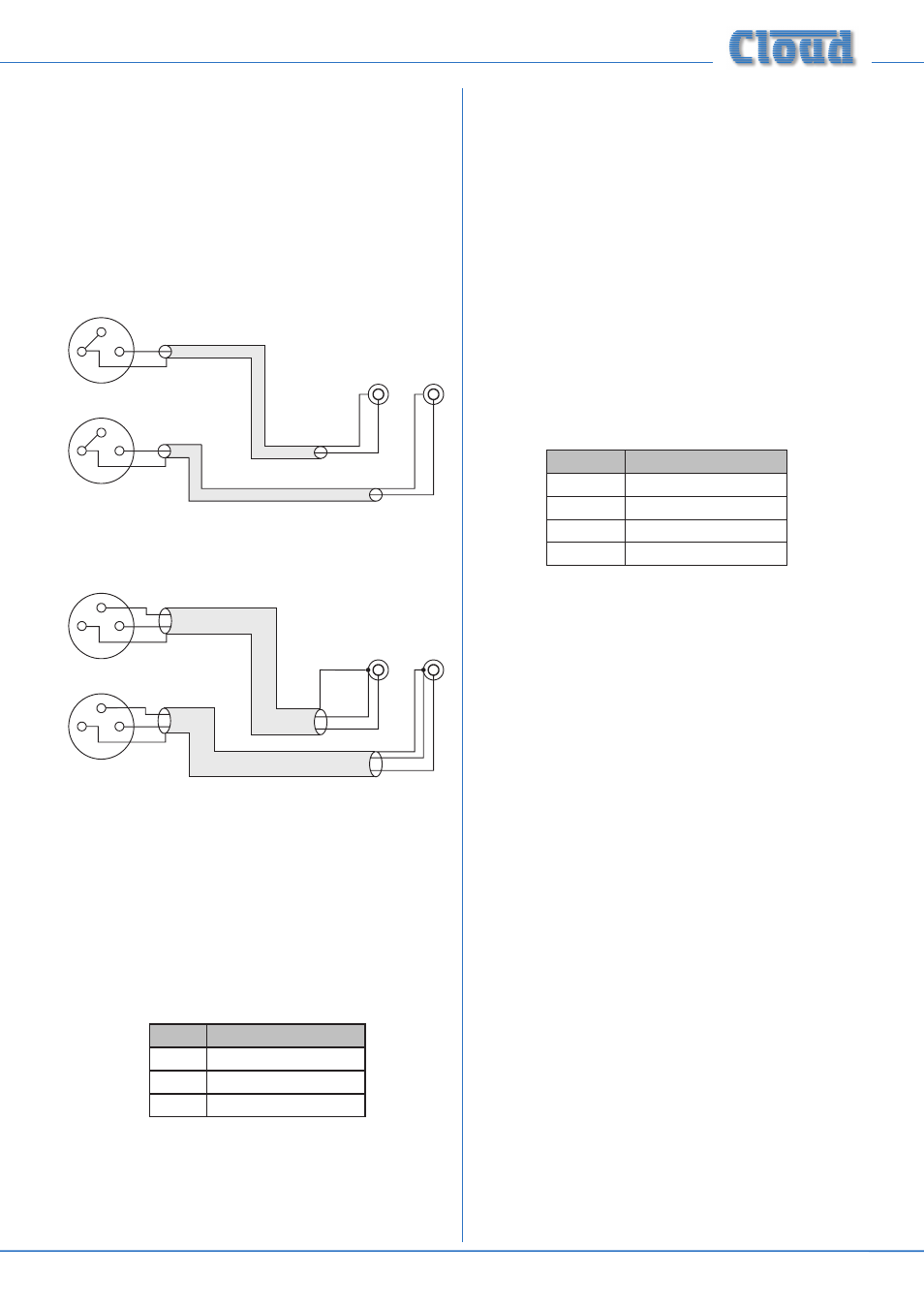
Connecting PM4/PM4-SA paging microphones
These microphones are equipped with both digital and
analogue paging interfaces; with the 36-50,
the analogue
interface is used. PM microphones are available in 4, 8, 12
or 16-zone versions; the installer should be sure he/she
understands how paging zones correspond to mixer zones
before commencing wiring. Although the 36-50 only supports
a maximum of three zones, there is no technical reason to
prevent a PM microphone being used in a restricted manner.
Standard two-core screened audio cable may be used for
the audio signal, and stranded multicore (3-core is adequate)
cable with an overall screen for the control cable. Note that
PM Series microphones cannot be powered from the 36-50,
and need an external PSU.
Connections on the PM microphone are made via the
rear cable access glands and screw terminal blocks on the
internal PCB (TERM2 and TERM 8 in the case of a PM4). Full
connection details can be found in the PM Series Installation
and User Guide.
The following diagram shows the cable connections between
a PM4 and a 36-50
.
Note that PM microphone must be
powered independently (either by a local PSU or via the
CDPM digital network from another PM unit); the 36-50 does
not have a facility for providing power to external accessories.