Music control, Connecting a pm1 paging mic, Connecting an rl-1 series remote control plate – Cloud Electronics 36-50 User Manual
Page 14
36-50 Installation and User Guide V1.0
14
TERM8
TERM2
H
O
T
C
O
LD
G
N
D
Z1
Z2
Z3
Z4
MICROPHONE
INPUT
Z1
Z2 UTIL
0 V
PM4 PAGING MICROPHONE
36-50
Z5
Z6
Z7
Z8
TERM1
0V
+V
1
3
2
Note that the default factory setting is for all three
ACCESS
port inputs to be permanently enabled. In order for the
36-50’s mic input to function correctly with a paging mic,
internal jumpers J2 (Zone 1), J3 (Zone 2) and Z4 (Utility
output) should be removed. See page 4 for jumper
locations.
For automatic music ducking during an announcement, set
the rear panel
PRIORITY switch to ON. See
page 18 for
further information.
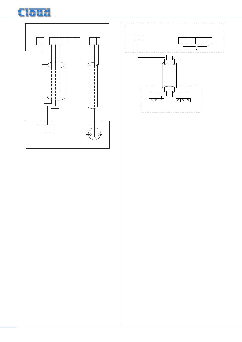
Connecting a PM1 paging mic
The PM 1 is a simple, passive paging microphone suitable
for situations where announcements are always made to
the same zone(s). It can be connected directly to the 36-50
Mixing Amplifier, the control cable being wired to the pin(s) of
the Zone Access port corresponding to the zone(s) in which
announcements are required. Any or all of the zones may be
paralleled if multiple zones need to operate from the PM1.
Either a single 2-pair individually-screened cable may be
used (this gives the neatest finish), or two separate standard
microphone cables. Connections on the PM1 are made via the
rear cable gland in the base and the screw terminal blocks on
the internal PCB (U2 and U3). Full connection details can be
found in the PM1 Installation and User Guide. Note that the
PM1 does not require DC power.
The following diagram shows the connections between a PM1
and a 36-50. Use of 2-pair cable is assumed; the same wiring
principle is adopted if separate cables are being used for audio
and control.
PAGING MIC INPUT
SCN COLD HOT
N/O N/C GND
U2 AUDIO
U3 ACCESS
ZONE ACCESS CONNECTOR
CONNECT TO
ZONE(S) IN USE
1 2 3
0V Z1 Z2 Z3 Z4 Z5 Z6 Z7 Z8 +V
36-50
PM1
Note that the default factory setting is for all three
ACCESS
port inputs to be permanently enabled. In order for the
36-50’s mic input to function correctly with a paging mic,
internal jumpers J2 (Zone 1), J3 (Zone 2) and Z4 (Utility
output) should be removed. See page 4 for jumper
locations.
For automatic music ducking during an announcement, set
the rear panel
PRIORITY switch to ON. See
further information.
Music control
Like many other Cloud products, the 36-50 allows remote
control of music level and source selection in each of the
primary zones. Cloud remote control plates from the RL-1
Series (music level only) and RSL-6 Series (music level and
source selection) provide an elegant solution, though control
via a DC voltage from third-party systems is also possible (see
page 19).
Both types of plate connect via the REMOTE SOURCE &
LEVEL port for the relevant zone (see [10] on page 11).
This connector is a 3-pin 5 mm-pitch screw terminal type.
Please refer to page 19 for additional information regarding
cable lengths, etc.
Connecting an RL-1 Series remote control plate
Wire the remote control plate as shown below. Either single-
core screened or twin-and-screen cable may be used; in the
case of the latter, ignore one of the cores. Maximum reliable
cable run is 100 m.