Pcb jumper locations, Emc considerations, Ground loops – Cloud Electronics 36-50 User Manual
Page 22
36-50 Installation and User Guide V1.0
22
PCB jumper locations
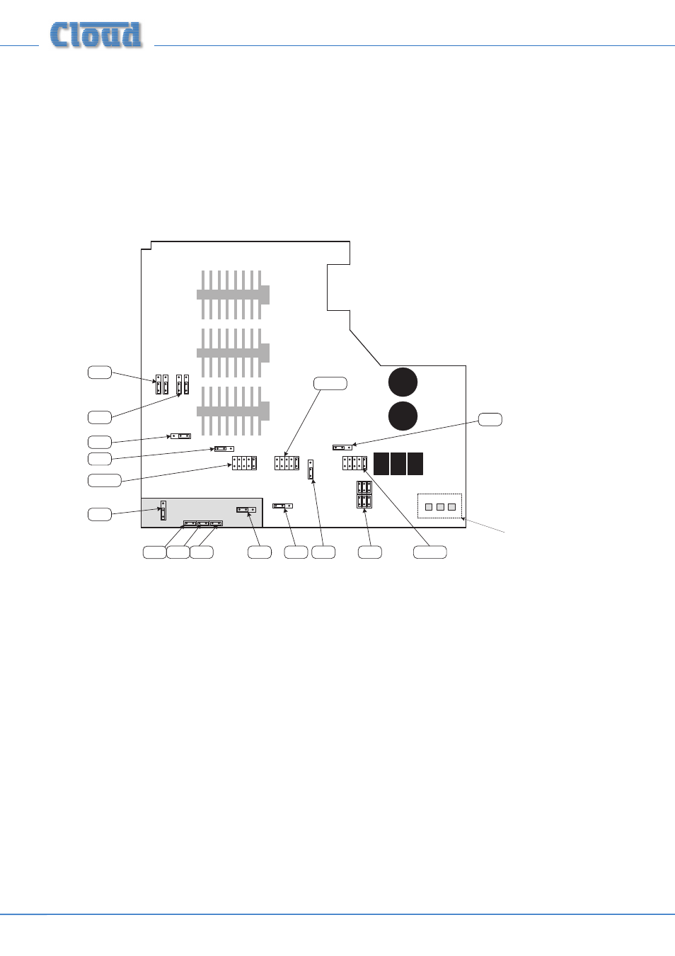
The diagram below shows the locations of the internal jumpers (not to scale) on the main PCB. The jumpers have two possible
positions; the black square in the symbol indicates the default setting. If any jumpers need to be changed, turn the Mixer Amplifier
off and disconnect it from the mains. Undo the 8 screws securing the top cover of the unit and remove it. Use a pair of small
pliers to gently remove the jumpers from the PCB headers and reposition them. Refit the top cover using the original screws.
The diagram also shows the locations of the socket for the optional loudspeaker EQ cards (CON2, CON3 & CON4).
O
FF
O
N
J1
(below sub-board)
J2
J4
J3
(below sub-board)
OFF ON
J5
SW FR
J6
(below sub-board)
SW FR
J7
O
FF
O
N
J8
OFF ON
J9
J10
O
FF
O
N
O
FF
O
N
J13
J12
6S 3S
J11
NOT TO SCALE – ONLY PRIMARY
COMPONENTS SHOWN
CON4
CON3
CON2
Headers for connection of
CXL-3120 transformer module
EMC considerations
The Cloud 36-50 fully conforms to the relevant electromagnetic compatibility (EMC) standards and is technically well behaved;
you should experience no operational problems and under normal circumstances, no special precautions need to be taken.
If the unit is to be used within close proximity to potential sources of HF disturbance such as high power communications
transmitters, radar stations and the like, the performance of the mixer may be reduced; we suggest that the microphone cable
screen be connected to the shell of the XLR type connector and the line input leads are kept as short as possible.
Ground loops
If, despite your best efforts, the completed sound system ‘hums’ you probably have a ‘ground loop’. The offending signal source
can often be identified by setting the volume control to minimum, then disconnecting the input leads (both left & right channels)
on each line input until the ‘hum’ disappears. This problem is often caused by terminating a screened input cable into a signal
source positioned a significant distance from the mixer. A good way of avoiding this potential problem is to use signal sources
(typically ‘consumer’ equipment) that are double insulated with no connection to the mains supply earth. If a signal feed were
derived from a second mixer (a club or microphone mixer for example) it would be perfectly normal to expect this to be
earthed; we suggest that a transformer be used to isolate the signal and prevent a noisy loop (see page 12).