Music mute, Speaker outputs (lo-z) – Cloud Electronics 36-50 User Manual
Page 15
36-50 Installation and User Guide V1.0
15
1
2 3
REMOTE
SOURCE + LEVEL
1 2 3
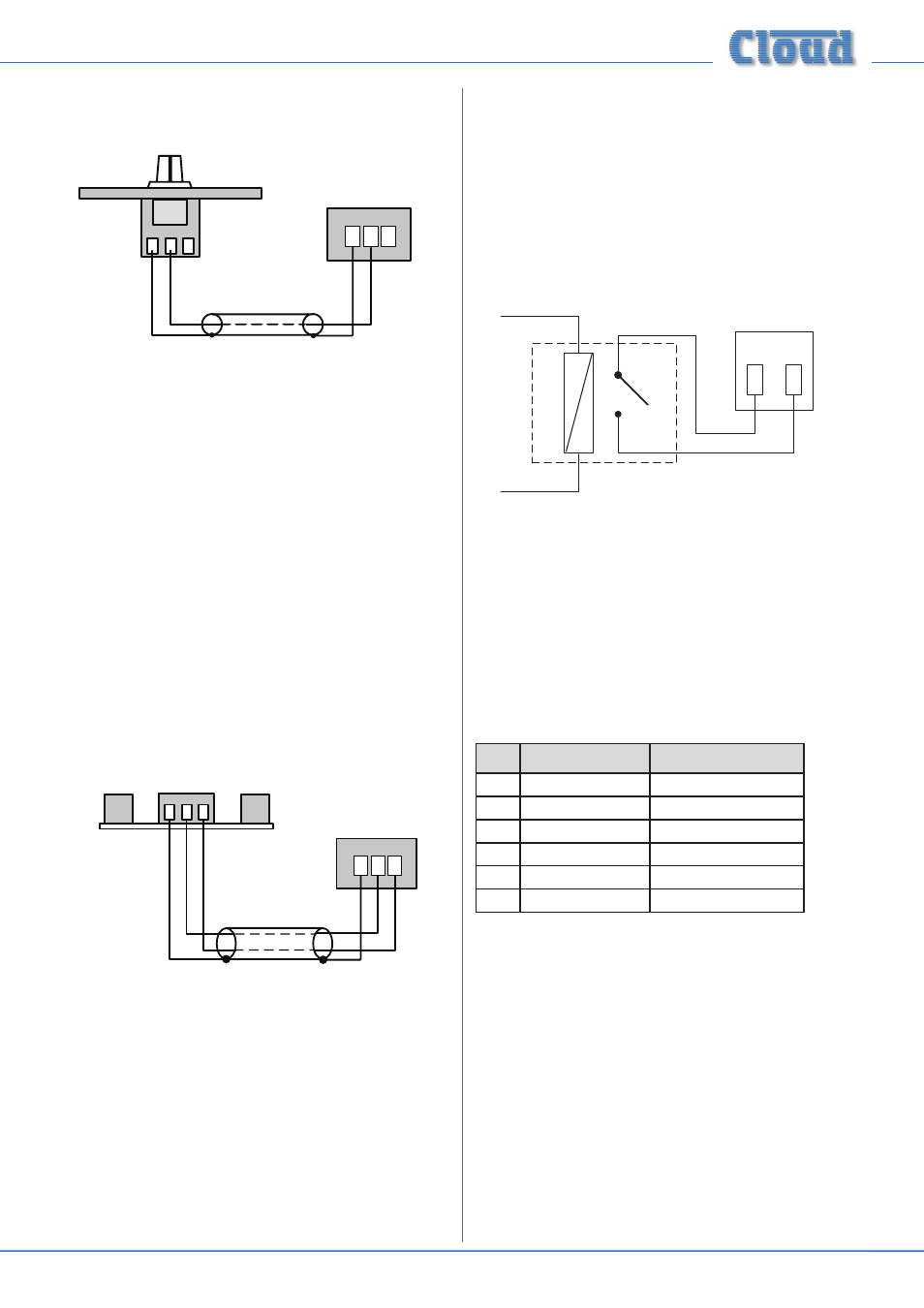
REMOTE LEVEL CONTROL WIRING
RL-1
SINGLE-CORE SCREENED CABLE MAY BE USED
Before the RL-1 will operate, the zone’s Music Control
Port must be enabled by setting the adjacent push-button
switch ([11] on page 11) to REMOTE (i.e., pressing it in).
In this setting, the zone’s front panel
MUSIC LEVEL and
SOURCE SELECT controls become inoperative. As music
source selection will still be required from the mixer’s front
panel when an RL-1 is in use, the REMOTE setting may be
overridden
for the source selection control only by moving
internal jumper J6 (Zone 1) or J7 (Zone 2) on the internal
PCB. See page 4 for location of internal jumpers.
Connecting an RSL-6 Series remote control plate
Wire the remote control plate as shown below. Twin-and-
screen cable should be used. Maximum reliable cable run is
100 m.
1 2 3
REMOTE SOURCE & LEVEL CONTROL WIRING
RSL-6
USE TWO-CORE SCREENED CABLE
1 2 3
REMOTE
SOURCE + LEVEL
Before the RSL-6 will operate, the zone’s
MUSIC CONTROL
port must be enabled by setting the adjacent push-button
switch ([11] on page 11) to REMOTE (i.e., pressing it in).
In this setting, the zone’s front panel
MUSIC LEVEL and
SOURCE SELECT controls become inoperative.
Music Mute
External muting of music is available at the
MUSIC MUTE
connector. National or Local Authority regulations governing
such systems may require that normal programme material
(i.e., music) should be muted in an emergency, to ensure that
any emergency messages are clearly audible.
The
MUSIC MUTE input is on a 2-pin 5 mm-pitch screw-
terminal connector. It should be connected to the appropriate
alarm output on whichever building management system
registers the alarm (typically the Fire System). The alarm
output must be volt-free; if no such output is available, an
intermediate relay or other isolation device must be installed
between the alarm output and the
MUSIC MUTE input.
1
2
MUSIC MUTE
INPUT
RE
LA
Y
NORMALLY OPEN (NO)
CONNECTION
Speaker outputs (Lo-Z)
The speaker output connector is a 6-pin, 5 mm-pitch screw-
terminal connector. Mating connectors are supplied. The
power amplifier outputs of both primary zones and the Utility
Output are present on this connector. Connect to speakers
using pairs of terminals as shown in the table:
Panel marking
Connect to:
1
0V
Zone 1 output ‘-‘
2
Z1
Zone 1 output ‘+‘
3
0V
Zone 2 output ‘-‘
4
Z2
Zone 2 output ‘+‘
5
0V
Utility Output
6
UT
Utllity Output
Each output stage is designed to drive into an impedance
of not less than 4 ohms. Check the impedance of the
loudspeaker(s) in use and, taking into account any series and/
or parallel wiring, ensure that the total load on each channel
is not less than 4 ohms.
Speaker outputs (100/70 V-line
operation)
The 36-50 may be converted for 100 V/70 V-line operation
by the use of the Cloud CXL-3120 transformer module. This
module is fitted internally, and consists of three independent
transformers with separate flying leads, so any or all outputs
of the 36-50 may be converted to 100 V and/or 70 V-line
operation as required.