Setting up & operation, Music inputs, Gain & level – Cloud Electronics 36-50 User Manual
Page 16: Local/remote control
36-50 Installation and User Guide V1.0
16
The low impedance outputs are still active, but
should not have a load connected to them while
the 70 V/100 V-line outputs are in use.
In the 36-50T model variant, the CXL-3120 is pre-installed
at the factory, and wired for 70 V-line operation. This can
be changed to 100 V-line operation (per-output) if wished
by moving on-board links. Alternatively, the standard 36-50
model may be modified for 100 V/70 V-line operation by
retrofitting the CXL-3120 module, which is available from
Cloud Electronics as an option. Full installation instructions
are supplied with the module.
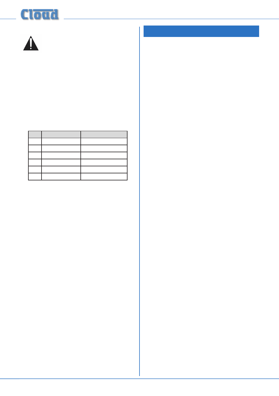
When the CXL-3120 is fitted, a 6-pin 5 mm-pitch screw-
terminal connector occupies the blank connector slot [13] at
page 11. The connector is wired as shown below:
Panel marking
Connect to:
1
Z1+
Zone 1 output ‘+‘
2
Z1-
Zone 1 output ‘-‘
3
Z2+
Zone 2 output ‘+‘
4
Z2-
Zone 2 output ‘-‘
5
UT+
Utility Output ‘+‘
6
UT-
Utility Output ‘-‘
If preferred, individual external transformers may be employed
to convert low impedance outputs to 100 V/70 V-line
operation. A suitable transformer is the CXL-40T, available
as an accessory from Cloud Electronics. A 19” rack tray for
mounting multiples of these is also available.
When using the 36-50 for 100 V/70 V-line operation, the
65 Hz high-pass filters in each zone to be used in this mode
should be enabled. See page 17 for full details.
SETTING UP & OPERATION
Music Inputs
Gain & level
To avoid dramatic changes in volume when switching between
sources, the 36-50’s music inputs are provided with preset
gain trim controls ([2] on page 11). These vary the input
sensitivity from -12 dBu (195 mV) to +8 dBu (2.0 V). When
setting the system up, play audio from all the sources in use
and listen to them one at a time in a convenient zone (ideally
that in which the mixer is located) at a reasonable volume.
Taking a source of “average” volume as the reference, the gain
controls of the others should be adjusted so that there is no
appreciable difference in volume between any of the sources.
(With a typical music source, setting the gain on its channel
to mid-way is a good starting point.) Note that consideration
may need to be given to the type of programme in use,
particularly if one or more sources are TV sound.
In normal operation, the music level in each primary zone
is set with the
MUSIC LEVEL control on the front panel
([2] on page 10). This control will not be operative if the
corresponding rear panel
MUSIC CONTROL push-button
is set to REMOTE. The music level at the Utility output is set
with the rear panel preset control ([9] on page 11).
Note that the setting of the music level has no effect on
microphone volume.
Local/remote control
If a zone has an RL-1 or RSL-6 Series remote control plate
connected in any zone(s), the corresponding rear panel
MUSIC CONTROL push-button(s) must be set to
REMOTE (button in) for the remote controls to be operative
and for the corresponding front panel controls to be disabled.
Zones without such plates should be set to LOCAL (button
out).
The setting of the internal PCB jumpers J6 and J7 is also
relevant. The default setting is SW. This means that the method
of zone music source selection will be determined by the rear
panel switch setting; the front panel control will make the
selection if
MUSIC CONTROL is set to LOCAL and via a
remote plate or other external control if set to REMOTE. If a
jumper is set to FR, the source selection will always be made
with the front panel control whatever is connected at the rear
panel or the setting of the
MUSIC CONTROL switch. If
external control of music level only (i.e., not source selection)
is required, J6 (Zone 1) and/or J7 (Zone 2) should be set to
FR and the
MUSIC CONTROL switch to REMOTE.
See page 4 for location of internal jumpers.
Note that independent remote control of music level or
source selection in areas fed by the Utility output is not
possible. However, the Utility Output can be “slaved” to
Zone 1’s source selection and level; the Utility output will
then follow any remote control in Zone 1. See page 17 for
more details.