Figure 2-1: p25 general system model, P25 general system model – Codan Radio P25 Training Guide User Manual
Page 24
TRAINING GUIDE | P25 RADIO SYSTEMS
Chapter 2: P25 Interface Standards
Page 16
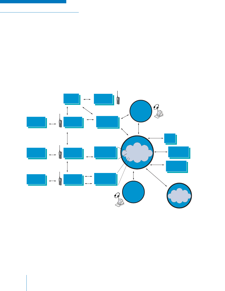
P25 defi nes six interfaces to an RF Sub-System (RFSS), one peripheral interface, and one over-the
air interface. These are shown in Figure 2-1 the P25 General System Model. Within the RFSS, all
equipment is unique to a single manufacturer. An example of a closed interface within the RFSS is
the interface between a trunking controller and its base station. Each of the open interfaces shown in
Figure 2-1 is defi ned in a TIA document.
The Inter Sub-System Interface (ISSI), Network Management Interface, Fixed Station Interface, and
Console Interface are being developed. It is TIA’s intention to standardize these equipment sub-system
interfaces whenever practical. The ISSI, console, and fi xed station interfaces are based on the use of
Internet Protocol (IP).
The general system model of a P25 compliant digital radio system defi nes the system elements plus
intra-system and inter-system interfaces and naming conventions of these elements and interfaces.
Figure 2-1: P25 General System Model
E
f
CONVENTIONAL
FIXED STATION
P25 GENERAL
SYSTEM MODEL
G
E
d
NETWORK
MANAGEMENT
E
n
E
t
G
ISSI =
Inter
Sub-System
Interface
PSTN
CAI =
Common Air
Interface
U
m
CONVENTIONAL
OR TRUNKED
FIXED STATION
DATA HOST
OR NETWORK
FSI =
Fixed Station
Interface
U
m
RF
SUB-SYSTEM
(RFSS)
OTHER
RF
SUB-SYSTEMS
SUBSCRIBER
RADIO
TRUNKED
FIXED STATION
REPEATER
U
m
SUBSCRIBER
RADIO
U
m
SUBSCRIBER
RADIO
U
m
U
m
DATA
PERIPHERAL
A
SUBSCRIBER
RADIO
U
m
U
m
U
m2
DATA
PERIPHERAL
A
DATA
PERIPHERAL
A
U
m
= Phase 1 FDMA CAI
U
m2
= Phase 2 TDMA CAI
CONVENTIONAL
CONSOLE
SUB-SYSTEM
E
f
E
c
CSSI = Console Sub-System Interface
TRUNKED
CONSOLE
SUB-SYSTEM