Logical link data unit 1, 240 bits – Codan Radio P25 Training Guide User Manual
Page 61
P25 RADIO SYSTEMS | TRAINING GUIDE
Chapter 4: Anatomy of the Common Air Interface Page 53
LOGICAL LINK DATA UNIT 1
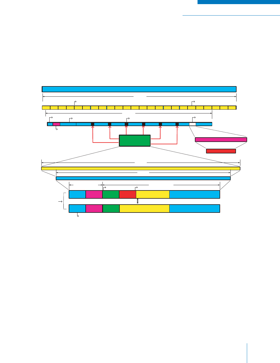
A diagram of Logical Link Data Unit 1 (LDU1) is given in Figure 4-6. LDU1 is the fi rst half of a superframe.
LDU1 is composed of the FS (48 bits), NID (64 bits), nine voice code words, numbered VC1 through
VC9 (1296 bits), Link Control Word (240 bits) and Low Speed Data (32 bits). Twenty-Four Status
Symbols are also interleaved throughout LDU1 yielding 1728 bits total. LDU1 takes 180 ms to transmit
at 9.6 kbps (the standard bit rate of the P25 CAI).
Figure 4-6: Logical Link Data Unit 1
The Link Control Word is constructed by serializing the information into 12 hex bits and then encoding
them with a (24,12,13) RS code to yield 24 hex bits. The 24 hex bits are then encoded with a (10,6,3)
shortened Hamming code to yield 240 bits total. The 240 bits of Link Control (LC) information is then
inserted in between the voice code words (VC2 to VC8) in blocks of 40 bits (LC 1-4 is a block of 40
bits, etc.).
LDU1 with Embedded Link Control (LC 72 bits + 168 bits parity = 240 bits)
1680 bits
VC1
VC2
VC3
VC4
VC5
VC6
VC7
LSD
VC9
240 bits
FS 48 bits
NID 64 bits
VC1 ~ VC9 each 144 bits
(88 Digital Voice IMBE + 56 bits Parity)
Low Speed
Data 32 bits
1728 bits
Status Symbol 2 bits Each for Every 70 bits (24 X 2 = 48 bits)
Each Block 70 bits
LC 1~4
LC 5~8
LC 9~12
LC13~16
LC 17~20
LC 21~24
Each 40 bits
Link Control Format (LCF) to specify the word's information
content (this shows two examples only)
16 bits Data
Shortened Cyclic Code (16,8,5)
RS (24,12,13)
Hamming Code (10,6,3)
2 octets (16 bits)
7 octets (56 bits)
144 bits
240 bits
LCF
$00
MFID
TGID 16 bits
Source ID 24 bits
Emergency bit
LCF
$03
MFID
Reserved
Destination ID 24 bits
Source ID 24 bits
VC8
Two examples of
Link Control Info
Service
Options
Service
Options
S