External connections, 3 external connections, Rear panel (standard configuration) – Comtech EF Data SMS-301 User Manual
Page 25: R s -301
SMS-301 Redundancy Switch
Installation
Rev. 3
2–3
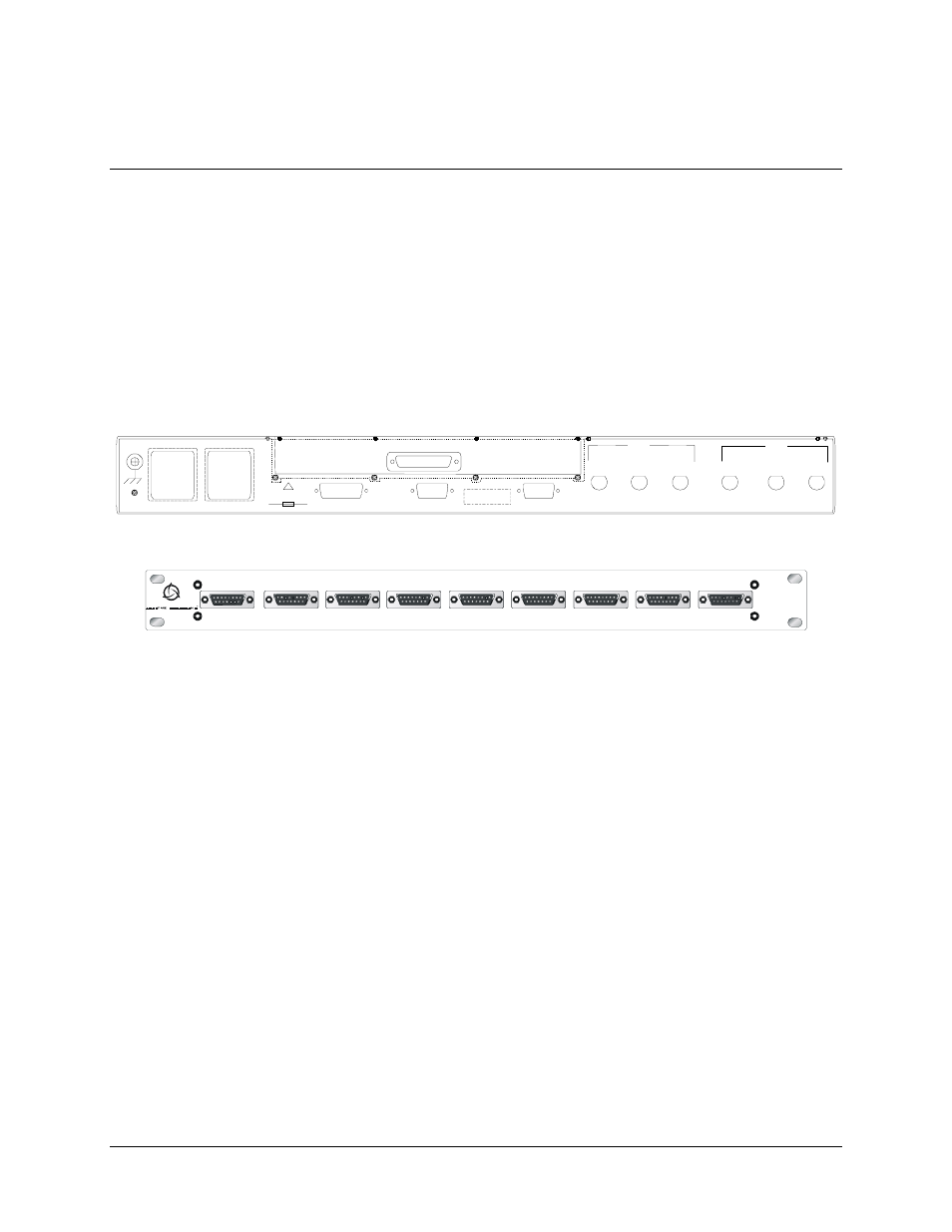
2.3 External
Connections
Connections between the 1:1 switch and other equipment are performed through the rear
panel connectors. These connectors vary depending on whether the Remote Switch (RS-
301) is used.
•
Refer to Table 2-1 for the connector list when the Data I/O is switched internal
to the 1:1 switch.
•
When the 1:1 switch is used with the Remote Switch (RS-301) option, refer to
Table 2-2.
J1 REM O TE SW IT CH CO N TRO L
STAT US/FAULT S
RE MOTE
CON TRO L
J1 4
AC 1
J11
AC2
J1 2
MO D EM
COM
J1 0
J1 3
J9
A
MO D
J8
RX IF
J7
B
J4
TX IF
J5
A
J6
B
!
10 0 TO 240 V
1.5 A 5 0 TO 60 Hz
T2A , 250 V
DE MOD
Rear Panel (Standard Configuration)
TRIB 1 DATA
TRIB 2 DATA
TRIB 3 DATA
TRIB 4 DATA
TRIB 5 DATA
TRIB 6 DATA
TRIB 7 DATA
TRIB 8 DATA
AUX
J9
J8
J7
J4
J1
J2
J3
J5
J6
R S -301
Rear Panel (With RS-301 Option)
Figure 2-1. SMS-301 Rear Panel Configurations