Comtech EF Data SMS-301 User Manual
Page 29
SMS-301 Redundancy Switch
Installation
Rev. 3
2–7
2.3.2.2
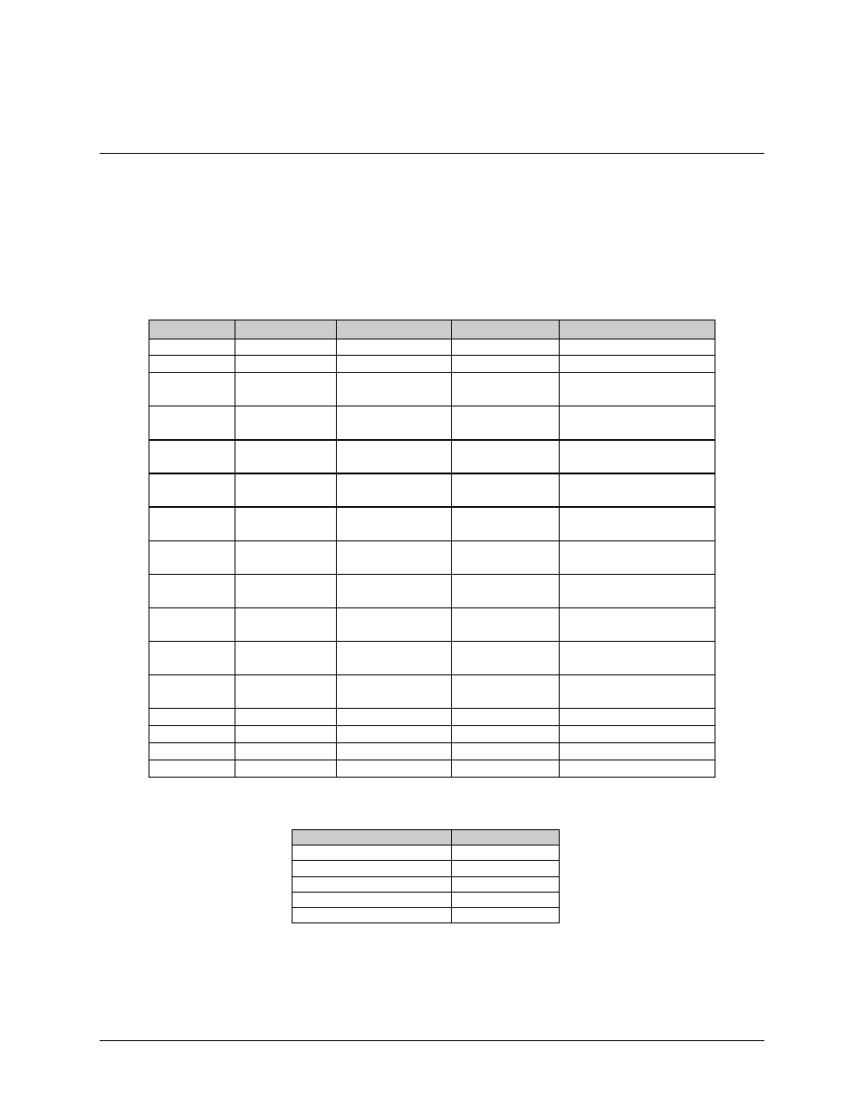
Data I/O Connector (J1, J2, J3), 37-Pin (PL/5952)
Note: For EIA-422/-449, V.35, and G.703 applications.
The 37-pin D subminiature connector pin assignments are shown in Table 2-5.
Table 2-5. Data I/O Connectors, 37-Pin
Pin #
EIA-422/-449
V.35
G.703
Signal Function
1
SG
SG
SG
Signal Ground
3
MF
MF
MF
MOD Fault
4
22
SD-A
SD-B
SD-A
SD-B
SD-A
SD-B
Send Data
5
23
ST-A
ST-B
ST-A
ST-B
Send Timing
6
24
RD-A
RD-B
RD-A
RD-B
RD-A
RD-B
Receive Data
7
25
RS-A
RS-B
RS-A
RS-B
Request to Send
8
26
RT-A
RT-B
RT-A
RT-B
Receiver Timing
9
27
CS-A
CS-B
CS-A
CS-B
Clear to Send
11
29
DM-A
DM-B
DM-A
DM-B
Data Mode
13
31
RR-A
RR-B
RR-A
RR-B
Receiver Ready
17
35
TT-A
TT-B
TT-A
TT-B
Terminal Timing
16
34
MC-A
MC-B
MC-A
MC-B
MC-A
MC-B
Master Clock
(Input)
19
SG
SG
SG
Signal Ground
20
SG
SG
SG
Signal Ground
21
DF
DF
DF
DEMOD Fault
37
SG
SG
SG
Signal Ground
The following shows the jumper configurations for EIA-422/449, V.35, and G.703.
EIA-422/449/V.35
G.703
JP2
JP1
JP3
JP6
JP4
JP7
JP5
JP6
JP9