Chapter 2 – DFI HU101 User Manual
Page 13
www.dfi .com
13
Chapter 2 Hardware Installation
Chapter 2
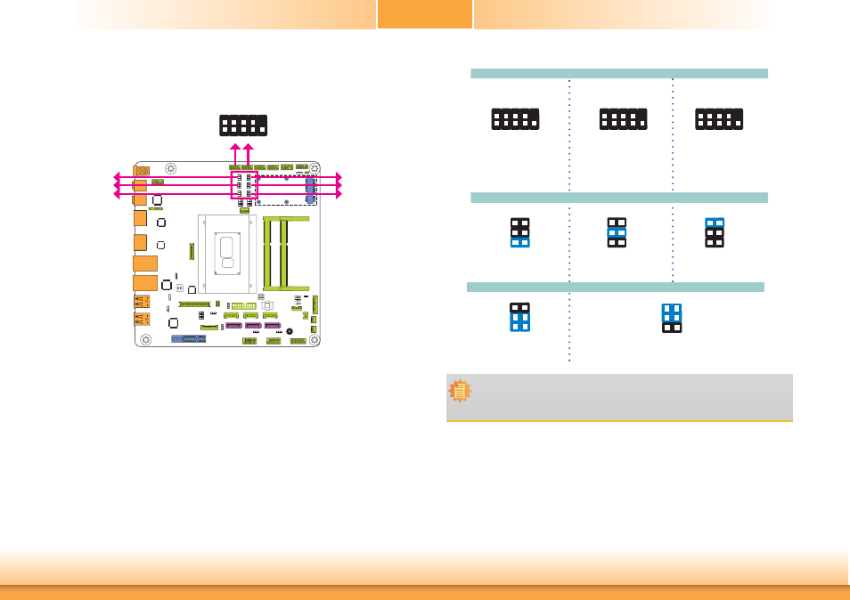
COM 1/COM 2 RS232/422/485 Select
2
1
9
These jumpers allow you to configure the Serial COM ports to RS232, RS422 (Full Duplex) or
RS485. JP3, JP5 and JP6 are used to configure the Serial COM port 1. JP7, JP9 and JP10 are
used to configure the Serial COM port 2. The pin functions of Serial COM port 1 and COM port
2 will vary according to these jumpers’ setting.
6
4
2
5
3
1
1-3, 2-4 On:
RS232 (default)
3-5, 4-6 On:
RS422 Full Duplex/RS485
Note:
When COM 1 RS232/422/485 is selected, JP5 and JP6 must be set in accordance to
JP3. And when COM 2 RS232/422/485 is selected, JP9 and JP10 must be set in ac-
cordante to JP7.
6
4
2
5
3
1
COM 1/COM 2:
RS232/422/485
JP5
JP3
JP6
JP9
JP7
JP10
COM 1
COM 2
JP3 (for COM 1) / JP7 (for COM 2)
RS485
COM 1/ COM 2
1-2 On: RS232
(default)
1
3
5
2
4
6
RS422
Full Duplex
3-4 On: RS422
Full Duplex
1
3
5
2
4
6
5-6 On: RS485
1
3
5
2
4
6
RS232
2
1
9
RXD
DCD- TXD
D
TR
-
GND
DSR
-
RT
S-
CTS-
RI
-
2
1
9
RXD-
RXD+ TXD+
TXD-
NC.
NC.
NC.
NC.
NC.
2
1
9
D
ATA
-
D
ATA
+
TXD
NC.
NC.
NC.
NC.
NC.
NC.
JP5 and JP6 (for COM 1) / JP9 and JP10 (for COM 2)