Chapter 2 – DFI HU101 User Manual
Page 24
www.dfi .com
24
Chapter 2 Hardware Installation
Chapter 2
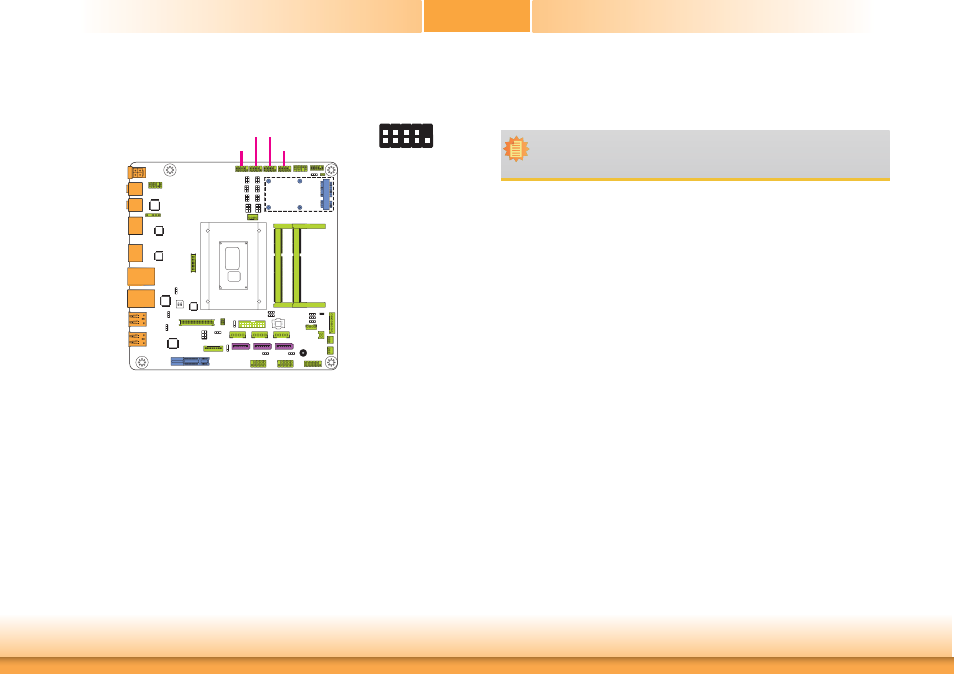
COM (Serial) Ports
COM 3 and COM 4 are fixed at RS232.
The pin functions of COM 1 and COM 2 ports will vary according to jumpers’ setting. JP3, JP5
and JP6 are used to configure the Serial COM port 1. JP7, JP9 and JP10 are used to config-
ure the Serial COM port 2. JP4 (for COM 1) and JP8 (for COM 2) are used to configure Serial
COM ports to pure RS232 or RS232 with power. Refer to “COM 1/COM 2 RS232/RS422/RS485
Select” and “COM 1/COM 2 RS232/Power Select“ in this chapter for more information.
The serial ports are asynchronous communication ports with 16C550A-compatible UARTs that
can be used with modems, serial printers, remote display terminals, and other serial devices.
Connecting External Serial Ports
Your COM port may come mounted on a card-edge bracket. Install the card-edge bracket to
an available slot at the rear of the system chassis then insert the serial port cable to the COM
connector. Make sure the colored stripe on the ribbon cable is aligned with pin 1 of the COM
connector.
COM 1/COM 2:
RS232/422/485
COM 4
COM 3
COM 1
COM 2
COM 3/COM 4:
RS232
2
1
9
RXD
DCD- TXD
D
TR
-
GND
DSR
-
RT
S-
CTS-
RI
-
BIOS Setting
Configure the serial COM ports in the Advanced menu (“Super IO Configuration” submenu) of
the BIOS. Refer to the chapter 3 for more information.
Note:
When COM 1 RS232/422/485 is selected, JP5 and JP6 must be set in accordance to
JP3. And when COM 2 RS232/422/485 is selected, JP9 and JP10 must be set in ac-
cordante to JP7.