Chapter 2 – DFI KB160 User Manual
Page 15
Advertising
www.dfi .com
15
Chapter 2 Hardware Installation
Chapter 2
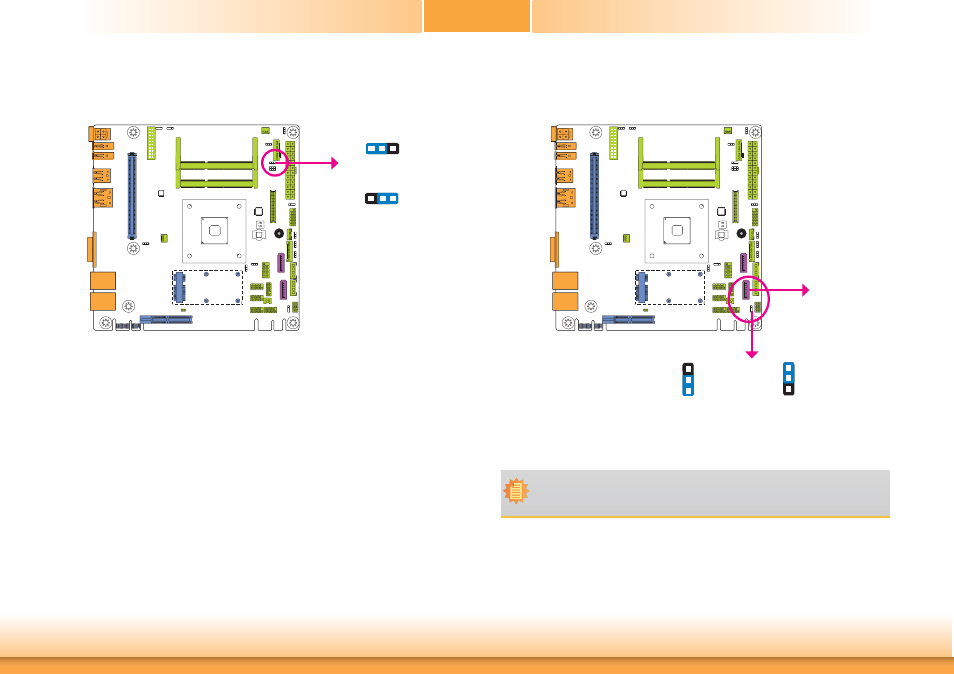
LCD/Inverter Power Select
2-3 On: +5V (default)
1-2 On: +12V
1
3
2
1
3
2
JP9 is used to select the power level of the LCD/Inverter power connector.
SATA DOM Power Select
Note:
1. SATA port 1 provides adequate space for SATA DOM.
2. When SATA port 1 does not operate as the SATA DOM device, JP6 must be set to
pins 1-2.
JP6 is used to select the power level of SATA DOM.
1-2 On: GND (default)
2-3 On: +5V
JP6
SATA 1
1
3
2
1
3
2
JP9
Advertising
This manual is related to the following products: