Chapter 2 – DFI KB160 User Manual
Page 27
Advertising
www.dfi .com
27
Chapter 2 Hardware Installation
Chapter 2
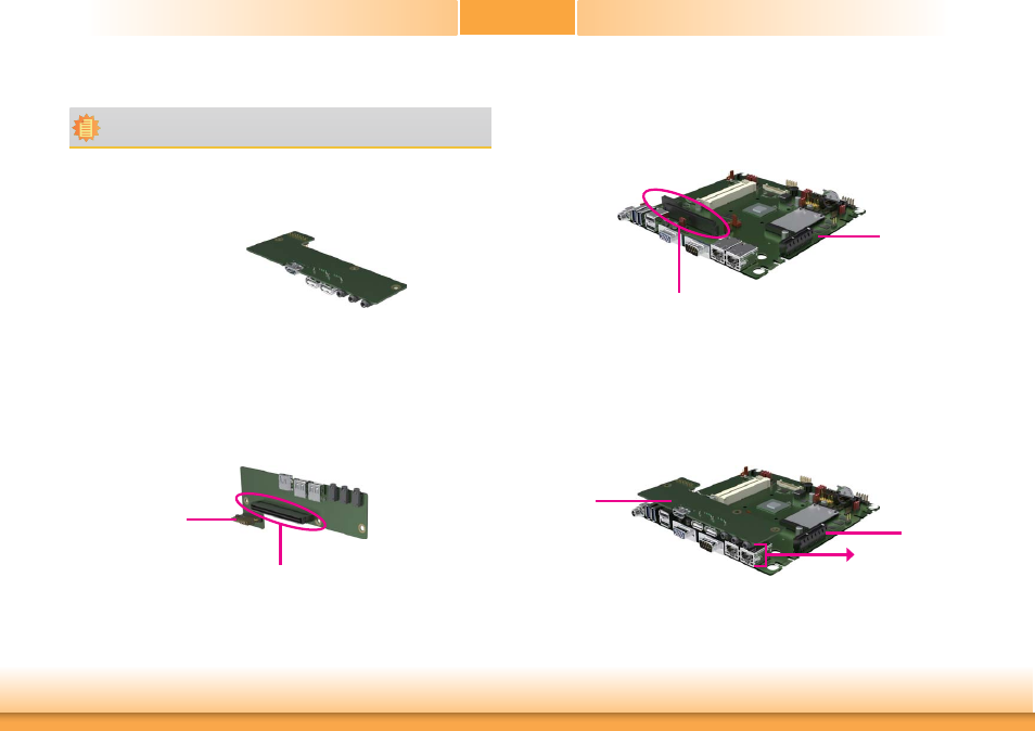
Installing an EXC Board into the EXC Interface for I/O Expansion
EXC Board
1 PCIe x1
1 DDI
1 High Definition Audio
2 Serial COM ports
1 PS/2 Keyboard/Mouse
1 USB 2.0
1 SMBus
1 LPC
Note:
The system board used in the following illustrations may not resemble the actual one.
These illustrations are for reference only.
The EXC board is designed for each customer to expand the I/O capability via the EXC interface.
EXC board
Motherboard
Motherboard
EXC interface
3. Insert the EXC board into the EXC interface on the motherboard for I/O expansion as the
photo illustrated below.
2. The EXC interface on the motherboard.
EXC interface
1. The EXC interface on the EXC board.
Power connector
Height: 20mm
Advertising
This manual is related to the following products: